Leave Your Message
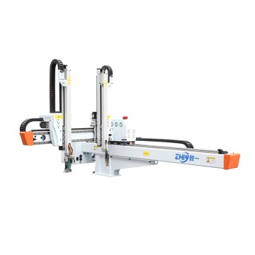

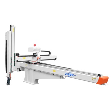
Three-Axis Servo Injection Molding Machine Robot Installation and Acceptance Standards
Three-Axis Servo Injection Molding Machine Robot Installation and Acceptance Standards
I. Pre-Installation Preparation: The Foundation for Acceptance
Adequate pre-installation preparation is crucial for ensuring smooth subsequent processes and successful acceptance. Strict control must be exercised over the environment, tools, and personnel.
Environmental Requirements: The installation site must be flat and firm, with a ground load-bearing capacity of at least 1.2 times the rated weight of the equipment to prevent vibration during operation. Sufficient operating space must be reserved, and the area around the robot's movement range must be free of obstructions. The ambient temperature should be controlled between 0-45℃, and the humidity between 5%-85% (non-condensing). The machine should be kept away from harsh environments such as dust and corrosive gases.
Tool and Accessory Inspection: Beforehand, verify that the Robot Body, servo driver, controller, connecting cables, fixing bolts, and other accessories are complete and that their models match the order. Prepare professional tools such as a level, torque wrench, multimeter, and oscilloscope, ensuring that the tool accuracy meets testing requirements.
Personnel Qualifications: Installation personnel must possess industrial robot installation qualifications, be familiar with the principles of a three-axis servo system, and have received professional training from the equipment manufacturer, clearly understanding the installation procedures and safety regulations.
II. Installation Process Standards: Follow Standards to Avoid Potential Risks
The installation process must strictly adhere to the operation manual, focusing on the three core steps: mechanical installation, electrical connection, and servo debugging. Each step must meet technical standards.
2.1 Mechanical Installation Standards
**Equipment Fixing:** Secure the robot arm base to the designated position on the injection molding machine using expansion bolts. Use a level to adjust the machine's levelness; both longitudinal and lateral horizontal errors should be ≤0.02mm/m to ensure no tilting or deviation during operation.
**Mechanical Connection:** Precisely align the robot arm with the injection molding machine's installation interface, ensuring a tight flange connection. Tighten bolts to the specified torque (typically 25-35 N·m, refer to the equipment manual for details), ensuring no looseness or gaps.
**Moving Part Inspection:** Manually move each axis to confirm that the arm, grippers, and other components move freely without jamming or abnormal noise. Ensure limit devices are properly installed without deviation or damage.
2.2 Electrical Connection Standards
**Wiring Layout:** Power lines and signal lines should be laid separately with a spacing ≥30cm to avoid electromagnetic interference. The cables are securely fixed, with bending radii meeting requirements (≥10 times the cable diameter), and there is no pulling or squeezing.
Wiring Standards: Wiring must strictly follow the electrical schematic diagram. Terminals must be securely crimped, clearly numbered, and grounding resistance ≤4Ω. The positive and negative terminals of the servo motor, driver, and controller power supplies must not be reversed, and communication lines must be correctly connected.
Safety Circuit Check: Confirm that the emergency stop button, safety door interlock, overload protection, and other safety devices are properly wired, the circuit is conductive, and there are no short circuits or open circuits.
2.3 Servo System Debugging Key Points
Parameter Configuration: Import the equipment's preset parameters through the controller, including the travel, speed limit, acceleration, and positioning accuracy of each axis, ensuring that the parameters match the production requirements of the injection molding machine.
Axis Motion Debugging: Start each axis servo motor individually to test the smoothness of forward and reverse operation, ensuring no shaking or abnormal noise, and rapid positioning response. During linkage testing, the movements of each axis are coordinated without interference.
Load Test: Simulating actual production conditions, after applying the rated load, the stability of the robot arm's operation is tested. The servo system should have no overload alarms, and current fluctuations should be within the allowable range (≤10% of rated current).
III. Core Acceptance Standards: Quantitative Indicators + Practical Testing
After installation, the equipment must undergo dual verification through quantitative testing and practical testing to ensure it meets factory standards and usage requirements. Delivery is only permitted after successful acceptance.
3.1 Key Quantitative Indicator Acceptance
Positioning Accuracy: Repeatability of each axis ≤±0.02mm, single positioning error ≤±0.03mm, measured at multiple points across the entire stroke range using a laser interferometer or dial indicator.
Operating Speed: Under no-load conditions, the maximum speed of each axis should conform to the equipment parameters (typically 500-800mm/s), acceleration time ≤0.3s, with no speed decay or sudden changes.
Load Capacity: Under rated load (typically 5-20kg, depending on the equipment model), continuous operation for 1 hour should result in no deformation or abnormal noise from the robot arm, and no overheating alarms from the servo drive.
Safety Performance: Emergency stop response time ≤0.1s; equipment can only start after the safety door is closed; overload, overcurrent, and short circuit protection functions trigger normally, with no safety hazards.
3.2 Practical Testing and Acceptance Process
No-load Cycle Test: 200 consecutive no-load cycles; all axes move in coordination without jamming or errors; positioning accuracy remains stable.
Simulated Production Test: Simulate processes such as part picking, placement, and transfer using an injection molding machine; test the continuity and accuracy of actions; part picking repeatability error ≤±0.05mm; no part dropping or mold collision.
Durability Test: Continuous operation for 8 hours; equipment runs smoothly; oil temperature and motor temperature ≤60℃; controller has no fault alarms; all performance indicators show no significant degradation.
Document Acceptance: Verify that the equipment's certificate of conformity, installation manual, electrical schematic diagram, parameter configuration table, parts list, and other documents are complete and consistent with the actual equipment information.
IV. Post-Acceptance Precautions: Ensuring Stable Operation
After successful acceptance, complete the final steps to support the dealer's subsequent delivery to customers and reduce usage risks.
Equipment Cleaning: Clean up dust and debris generated during installation, wipe the equipment surface, and check that all lubrication points have sufficient lubricant to ensure smooth operation.
Training and Briefing: Provide operational training to dealers or end customers, focusing on the equipment operation procedures, parameter adjustment methods, daily maintenance points, and safety precautions. Keep training records.
Warranty and After-Sales Coordination: Clarify the equipment warranty period (usually 12-24 months), provide after-sales contact information and repair procedures, and provide a list of vulnerable parts for easy maintenance and replacement.
Website:https://www.zhiyirobotics.com/
#Molding Machine Robot#Multi Axis Robot Arm#Robot Arm For Injection Molding Machine#3 Axis#3 Axis Articulated Robot