Leave Your Message
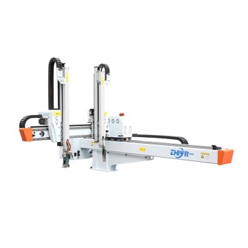
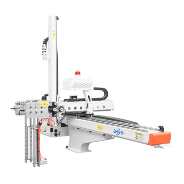

Three-Axis Robot Quick Installation Guide
Three-Axis Robot Quick Installation Guide
Introduction: The Core Value of Rapid Installation and Compliance For injection molding manufacturers, the efficient installation of three-Axis Robots directly determines the efficiency of automation upgrade implementation. Adhering to international safety standards (ISO 10218-1/2) and European and American industrial standards (ANSI/RIA R15.06) can shorten the installation cycle, reduce downtime losses, and ensure long-term stable operation of equipment. This article will break down a rapid installation process for three-axis servo robots adapted to European and American production scenarios, balancing ease of operation and compliance, ensuring efficient installation.
#Three-axis robot, quick installation guide#Injection molding machine three-axis servo robot installation steps#ISO 10218-1 three-axis robot installation specifications#European and American standard three-axis robot commissioning process#injection molding machine servo Robot Electrical connection techniques

I. Pre-installation Preparation: Standardized Preparation Completed in 30 Minutes
1. Site and Working Condition Verification
Confirm that a maintenance passage of ≥80cm is reserved around the injection molding machine, the installation area is free of obstacles and meets load-bearing capacity to avoid movement interference. Power supply must be matched with three-phase 380V/50Hz (power supply) and single-phase 220V (control power supply), and the grounding system must meet the grounding resistance ≤4Ω requirement. Simultaneously prepare a dry, oil-free compressed air source with a stable pressure of 0.5-0.7MPa to provide power to pneumatic components.
2. Equipment and Accessory Inventory
Check the three-axis robot body, control cabinet, end effector (gripper/suction cup), mounting bracket, shielded cable, and other core components against the packing list, confirming no transportation damage and that key components such as servo motors and guide rails are intact. Pay special attention to verifying the firmware version's compatibility with the injection molding machine model to avoid compatibility issues affecting the installation schedule.
3. Technical Solution Confirmation
Determine the installation method (side-mounted, top-mounted, or floor-standing), and confirm no interference in the three-axis (X/Y/Z) motion range, considering mold dimensions and part removal paths. Familiarize yourself with the safety requirements of ISO 10218-1 in the equipment manual beforehand, and clarify the installation location and linkage logic of the emergency stop button and safety light curtain.
II. Core Installation Steps: Efficient Deployment in 4 Hours (Phase-by-Phase Practice)
1. Mechanical Installation: Precise Positioning and Rapid Fixing
Fix the base according to the installation type: For side-mounted installations, use high-strength bolts to secure to the injection molding machine template, with a verticality deviation ≤0.5mm/m; for top-mounted installations, install on the machine body beam; for floor-standing installations, directly fix to the load-bearing surface, requiring only 4 fixing points to meet stability requirements.
Body Assembly: After hoisting the columns and beams, use a laser level to calibrate the parallelism and verticality of the X/Y/Z axes. Install the guide rails, lead screws, and servo motors sequentially, ensuring uniform meshing clearance of the transmission components. The end effector is fixed via a flange, and the clamp opening and closing stroke or suction cup vacuum pressure is adjusted according to product characteristics.
Limit device installation: Mechanical limit blocks and photoelectric switches are installed at the extreme positions of movement. Safety guardrails and light grating sensors cover the movement area, meeting European and American industrial safety protection requirements.
2. Electrical and pneumatic connections: Standardized wiring to avoid interference.
Circuit connection: Professional electricians connect power cables according to color standards. Control cables must be wired separately from power lines, and the shielding layer is grounded at one end to prevent electromagnetic interference. Servo drivers, encoders, and control cabinet PLC and touch screen are precisely wired, and clearly labeled for easy future maintenance.
Injection molding machine signal integration: Achieve "mold opening → part removal → mold closing" signal linkage. The injection molding machine's mold opening signal triggers the robot arm's part removal action. After part removal, a feedback signal is sent to the injection molding machine to start the next cycle, ensuring smooth coordination.
Pneumatic connection: Air hoses are designed with expansion allowance. After connecting to the solenoid valve assembly, a pressure gauge and filter are installed. The pipeline is checked for leaks, and the response speed of the pneumatic components is adjusted.
III. Debugging and Verification: Standardized Calibration Completed in 30 Minutes
1. Parameter Initialization and Single-Axis Debugging
After powering on, complete parameter initialization on the touchscreen, setting axis type, travel range, and servo motor parameters. Jog the X/Y/Z axes independently, checking for any jamming or abnormal noise. Calibrate the zero point position, ensuring repeatability accuracy ≤ ±0.1mm, meeting injection molding production precision requirements.
2. End Actuator and Path Debugging
Test the clamp opening and closing force and suction cup adsorption force. Adjust pressure for high-precision products to avoid damage. Write a linear path program for picking up and placing parts, initially running at 50% of rated speed. Optimize the path to reduce idle travel and improve production cycle time.
3. Safety Function Verification
Test the emergency stop button, safety door interlock, and fault alarm functions. Simulate personnel accidentally entering a hazardous area to verify the immediate response capability of the safety system. After confirming compliance with OSHA industrial safety standards and the absence of residual safety hazards, proceed to the trial operation phase.

IV. Trial Run and Acceptance: Production Preparation Completed in 2 Hours
1. No-Load and Load Trial Run
First, conduct no-load linkage between the injection molding machine and the robotic arm to verify the timing matching of mold opening, part picking, and mold closing. After confirming no interference, load testing is performed by loading the mold. Run continuously for 2 hours, observing the product gripping stability and placement accuracy, and recording the operating parameters.
2. Performance and Compliance Acceptance
Test core indicators according to the technical agreement: load capacity, operating cycle time, and repeatability accuracy must meet the standards. Organize installation and commissioning records, electrical drawings, and other documents to ensure compliance with the ISO 10218-2 system integration standard, providing a basis for future maintenance and compliance checks.
3. Operation Training Key Points
Explain basic equipment operation, parameter adjustment, and emergency handling procedures to operators, with a focus on safety regulations and daily inspection methods, ensuring personnel master standardized operating skills.
Conclusion: Key Advantages and Precautions of Rapid Installation
Following this guide enables the efficient implementation of a three-axis robot in "4 hours of installation + 30 minutes of debugging + 2 hours of trial operation," reducing time by 50% compared to traditional processes. The key lies in adhering to international safety standards, standardized operating procedures, and precise calibration, ensuring both installation speed and long-term operational stability and compliance.
For batch installations or complex working conditions, it is recommended that professional technicians provide on-site guidance to ensure that every step of the operation complies with European and American industrial standards and equipment technical requirements, maximizing the automation value of the three-axis servo robot.