Leave Your Message
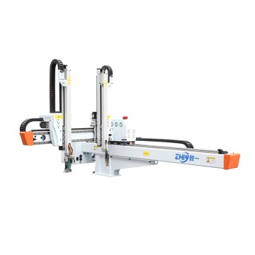
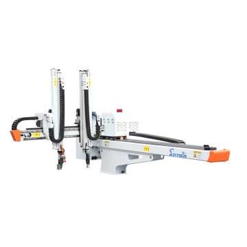
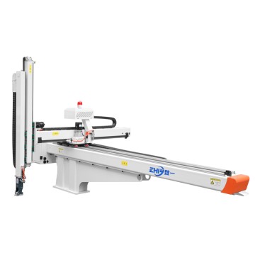

The Mechanical Structure of a Five-Axis Injection Molding Robot
The Mechanical Structure of a Five-Axis Injection Molding Robot: A Core Analysis of Precision Drive and Efficient Collaboration
In modern injection molding automation, five-axis injection molding robots, with their flexible, multi-dimensional operational capabilities, have become key equipment for improving production efficiency and reducing labor costs. Their exceptional performance is driven by a meticulously designed mechanical system—from the drive unit to the end effector—where the coordinated operation of each component determines the robot's performance in high-speed grasping, precise positioning, and complex trajectory motion. This article will provide an in-depth analysis of the core mechanical structure of a five-axis injection molding robot, revealing the inherent connection between equipment performance and structural design, helping companies make more accurate equipment selection decisions during automation upgrades.
Basic Architecture: The "Skeleton Framework" of the Five-Axis Motion System
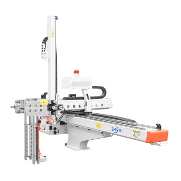
The mechanical structure of a five-axis injection molding robot is based on a multi-joint linkage system. By combining three linear axes (X, Y, and Z) with two rotary axes (A and B), it achieves full range of motion in three dimensions. This architecture transcends the motion limitations of traditional three-Axis Robots, demonstrating significant advantages in handling unusually shaped injection molded parts and removing parts from complex molds.
Linear axis modules: The X-axis (lateral movement), Y-axis (forward and backward extension), and Z-axis (vertical lift) typically utilize a combination of high-precision linear guides and ball screws. The guides are made of hardened alloy steel with a precision-ground surface. Combined with sliders with adjustable preload, they ensure linearity errors within 0.02mm/m during movement. The ball screws are directly connected to the drive motor via nuts, converting rotational motion into linear displacement. This achieves transmission efficiency exceeding 90%, significantly higher than traditional rack and pinion systems, effectively reducing energy loss.
Rotary axis joints: The A-axis (wrist rotation) and B-axis (arm swing) are the core elements for complex posture adjustments. High-precision harmonic reducers are used within the joints, with backlash controlled to within 1 arc minute. Combined with the radial and axial load capacity of the crossed roller bearings, they ensure both rigid rotational output and 0.1° positioning accuracy. In high-speed operation scenarios, the dynamic response speed of the rotating axis can reach 500°/s, meeting the demands of rapid changeover production.
Drive System: The "Muscle Tissue" of Power Output
The drive system of a five-axis robot acts like a "muscle," providing precisely controlled power for each axis' movement. Currently, mainstream drive solutions are categorized as servo motors and stepper motors. Servo drives, with their advantages in closed-loop control, dominate high-end injection molding production.
Servo drive units consist of a servo motor, encoder, and driver. The motor utilizes rare earth permanent magnets, offering high torque density and stable power output even at low speeds. The encoder resolution typically reaches 20 bits (1,048,576 pulses per revolution). Combined with the driver's PID control algorithm, this achieves a position control error of ≤0.01mm. In high-speed part removal scenarios, the servo system's acceleration and deceleration times can be controlled within 0.1s, meeting cycle times exceeding 120 cycles per minute.
Transmission Connection Design: The drive system and the moving axis are connected via a flexible coupling or synchronous belt. Elastic couplings can compensate for installation misalignment and reduce the impact of shock loads on the motor. Synchronous belt drives are suitable for long-distance power transmission. Their polyurethane belt body and steel wire core structure ensure transmission accuracy while withstanding wear and tear over 10,000 hours of continuous operation.
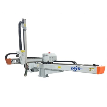
End Effector: The "Hand" of Operational Interaction
The end effector (gripper) is the component that directly interacts with the Robot Arm and the injection molded part. Its structural design must be customized according to the product's characteristics. Common types include pneumatic grippers, vacuum suction cups, and magnetic devices. Its key focus is on rapid switching and stable collaboration with the robot arm.
End Effector Structure: The pneumatic gripper uses a dual-piston drive with an adjustable gripping force range of 5-500N. It is equipped with silicone or polyurethane fingers to accommodate injection molded parts of varying materials and shapes. The vacuum suction cup uses a Venturi generator to generate a negative pressure of -80kPa. A single gripper can hold over 5kg, making it particularly suitable for large, flat plastic parts. Some high-end models are equipped with quick-change interfaces, reducing changeover time to under 30 seconds, meeting the needs of high-variety, low-volume production.
Load-balancing design: A load sensor is installed at the connection between the end effector and the forearm to monitor the gripping weight in real time. When the load exceeds a set threshold (typically 120% of the rated load), the system automatically triggers a protection mechanism, halting movement and issuing an alarm to prevent damage to the mechanical structure due to overload. This design allows the robot to accommodate loads ranging from 5 to 50 kg, covering production needs ranging from small electronic components to large automotive plastic parts.
Support structure: The "torso" that ensures stability
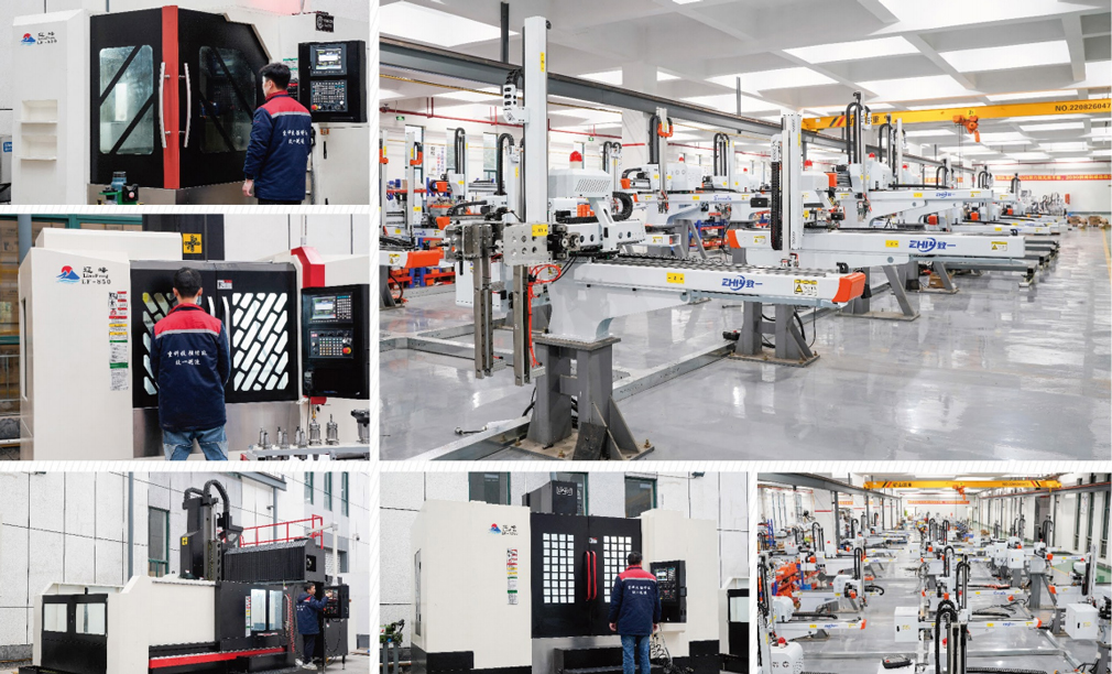
The support structure includes load-bearing components such as the base, columns, and beams. Its rigidity and lightweight design directly affect the robot's motion accuracy and energy consumption. Modern five-axis robots generally adopt a modular design, using finite element analysis to optimize structural stress distribution.
Material and material selection: Columns and beams are typically made of high-strength aluminum alloy profiles (such as 6061-T6), anodized for both corrosion and wear resistance. Steel reinforcements are embedded in key load-bearing areas, reducing overall weight by 30% while ensuring static deformation of ≤0.5mm/m. The base is constructed of cast iron, and aging treatment eliminates internal stresses, ensuring operational stability.
Vibration-absorbing and protective design: Shock-absorbing pads are installed at the connection between the support structure and the ground, absorbing over 90% of high-frequency vibrations. Retractable protective covers are installed around the moving parts, constructed from a multi-layer nylon canvas and metal frame composite structure. They achieve an IP54 rating and effectively protect against dust and oil contamination in the injection molding workshop.
Production Value Brought by Structural Advantages
The mechanical design of the five-axis injection molding machine robot ultimately serves to improve production efficiency and product quality. Its multi-axis linkage increases the optimization rate of the part removal path by 40%, enabling simultaneous grasping of parts from multiple stations in complex molds without cavity interference. High-precision positioning (repeatability ≤±0.05mm) reduces the risk of collision between parts and molds, reducing the defect rate to below 0.1%.