Leave Your Message
Is the performance of a three-axis servo injection molding machine robot degrading?
Is the performance of a three-axis servo Injection Molding Machine robot degrading?
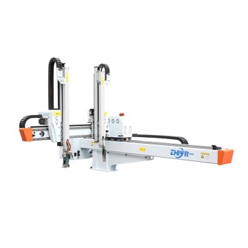
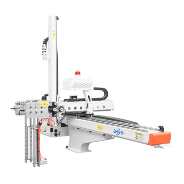
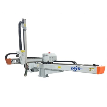
On an injection molding production line, a three-axis servo injection molding machine robot is a core piece of equipment that connects mold opening and closing, product placement, and conveying. Its performance stability directly determines production efficiency, product qualification rate, and equipment lifespan. When the robot experiences performance issues such as positioning accuracy deviation, slow speed, reduced load capacity, or movement lag, failing to quickly locate the root cause can not only cause production line downtime but also lead to secondary damage to components due to reckless repairs. This article will provide a systematic fault cause assessment solution from four perspectives: abnormal signal identification → module-by-module troubleshooting → fault verification → preventive maintenance, helping technicians efficiently resolve issues.
1. Early Diagnosis of Performance Abnormalities: First "Capture the Signal" Then "Lock the Scope"
Before beginning troubleshooting, it's important to identify the specific manifestations of performance degradation through observation and data collection to avoid wasting time by conducting indiscriminate troubleshooting. The following are common performance anomaly signals and their corresponding initial diagnosis areas:
1. Core Performance Anomaly Signal Classification
Positioning Accuracy Deviation: The robot deviates from the target position when grasping a product, fails to precisely align with the conveyor belt when placing it, or the repeatability error exceeds the specified value in the equipment manual (typically, the repeatability accuracy of a three-axis servo Robot Should be ≤±0.1mm). Initial suspicions: Servo system parameter drift, mechanical wear, and encoder signal abnormalities.
Operating Speed Reduction: When the robot is unloaded or loaded, the actual speed of each axis (X-axis horizontal, Y-axis vertical, and Z-axis vertical) is lower than the set value, and there are pauses during acceleration/deceleration. Initial suspicions: Servo drive current limiting, motor power loss, or increased load resistance.
Reduced Load Capacity: A product that could previously be grasped normally (e.g., a 5kg injection molded part) drops after grasping, or an overload alarm is triggered during operation due to excessive load. Initial suspicions: Insufficient servo motor torque, transmission slippage, or insufficient pressure in the pneumatic/hydraulic auxiliary system (if a pneumatic gripper is included). Action Response Delay: After the operator panel issues a command, the robot takes 1-3 seconds to execute an action, or there is a noticeable pause when switching between actions. Initial suspicions: Control system communication delay, sensor signal lag, and improper servo gain parameters.
2. Key Data Collection and Comparison
Visual inspection alone cannot accurately locate the problem; data comparison is necessary to narrow down the fault scope:
Record current operating parameters: Use the robot control system (such as the PLC touch screen or servo drive panel) to read data such as the operating speed, position deviation, motor current, and torque output of each axis. Compare these to the parameters during normal operation (refer to the device manual or historical operation records). Focus on indicators such as "abnormally high current," "position deviation exceeding the threshold," and "excessive torque fluctuation."
Statistical fault trigger conditions: Record whether performance degradation is associated with specific scenarios, such as "deviation only occurs under load," "speed slows down after 1 hour of operation," and "frequent failures occur when the ambient temperature rises." These conditions can help rule out unrelated factors (such as the impact of ambient temperature and humidity on electronic components).
2. In-depth Module-by-Module Troubleshooting: From "Core Components" to "Auxiliary Systems"
The performance of a three-axis servo injection molding machine robot depends on the coordinated operation of the "servo system → mechanical structure → control system → auxiliary systems." Troubleshooting requires module-by-module disassembly, verifying the functional integrity of each link one by one.
A. Core power source: Servo system troubleshooting (accounting for more than 60% of performance problems)
The servo system is the "power heart" of the robot, consisting of three parts: servo motor, servo drive, and encoder. Any abnormality in any component will directly lead to performance degradation. Troubleshooting should follow the logic of "from drive to motor, from signal to hardware": (1) Servo drive: first check the "alarm code" and then verify the "parameter setting"
Step 1: Read the alarm code: The servo drive panel will display the fault code (such as "AL.E6" of Mitsubishi MR-J4 series represents encoder failure, and "Err.11" of Panasonic A6 series represents overcurrent). Basic problems (such as overvoltage, overcurrent, overheating, and encoder communication abnormality) can be located by comparing with the equipment manual.
Step 2: Check key parameters: If there are no alarm codes but performance is degraded, focus on the following parameters:
Position loop gain (P Gain) and velocity loop gain (V Gain): Too low a gain will result in slow positioning response and large deviation; too high a gain may cause vibration. Fine-tune according to the recommended values in the device manual (usually adjust the velocity loop first, then the position loop).
Electronic gear ratio: An incorrect gear ratio setting can result in a mismatch between commanded position and actual position (for example, a set movement of 100mm but only 50mm). Verify that the gear ratio matches the mechanical transmission ratio (such as the ball screw lead).
Current and torque limit settings: If the drive is mistakenly set to "current limit mode" or the torque limit is too low, the motor output power will be insufficient, resulting in slow speed and reduced load capacity. Restore the default limit values or reset them based on load requirements.
B, Servo motor: Judging "hardware health" from "operating status"
Sensory inspection: When the motor is running, touch the motor housing with your hand (be careful to avoid burns). If the temperature exceeds 70℃ (normal temperature rise of servo motor is ≤40℃), it may be that the motor coil is aging, the bearing is worn, or the load is too large; listen to the running sound of the motor. If there is a "buzzing" or "friction" sound, it is likely that the bearing is lacking oil or is damaged. It is necessary to disassemble and inspect and replace the bearing (it is recommended to use imported bearings of the same model, such as NSK and SKF).
Performance test: Disconnect the motor from the transmission mechanism (no-load test). If the motor running speed and torque are normal when no-load, it means that the fault is at the mechanical load end; if it is still abnormal when no-load, use a multimeter to measure the resistance value of the three-phase winding of the motor (normally, the three phases should be balanced, with a deviation of ≤5%). If the resistance of one phase is infinite, it means that the winding is broken and the motor needs to be repaired or replaced.
C, Encoder: Signal "zero error" is the key to positioning accuracy.
The encoder is the "eye" of the servo system, responsible for feeding back the motor position and speed signals. Abnormal signals will directly lead to positioning deviation. Troubleshooting method:
Line inspection: Check the connection line between the encoder and the driver (usually a shielded cable) to see if there are loose connectors, damaged cables, or poor grounding of the shielding layer (if the shielding layer is not grounded, it will introduce electromagnetic interference and cause signal fluctuations). It is recommended to re-plug the connector and replace the damaged cable.
Signal test: Use an oscilloscope to measure the A, B, and Z phase output signals of the encoder. Under normal circumstances, it should be a stable square wave signal. If there is waveform distortion, pulse loss, or the amplitude is too low (less than 5V), it means that the internal components of the encoder are damaged and the encoder of the same model needs to be replaced (note that the encoder resolution must match the driver, such as 17 bits or 23 bits). 2. Force and motion transmission: Mechanical structure troubleshooting (easily overlooked "invisible killer") Even if the servo system is normal, wear, looseness or deformation of the mechanical structure will lead to performance degradation, because the movement of the manipulator needs to be transmitted through "motor → coupling → ball screw / synchronous belt → guide rail slider", and the loss of any link will weaken the power transmission efficiency: (1) Transmission mechanism: focus on "wear" and "concentricity" Ball screw: As the core transmission component of the X, Y, and Z axes, the wear of the screw will lead to "increased reverse clearance" (that is, when the motor rotates in the opposite direction, the manipulator has an empty stroke), which manifests as positioning deviation. Inspection method: Use a dial indicator to fix the slider and manually push the slider. If the dial indicator pointer fluctuates by more than 0.05mm, it means that the screw is seriously worn; at the same time, observe whether there are scratches, rust or dry grease on the surface of the screw. Special grease (such as lithium-based grease) needs to be added regularly. When the wear exceeds the limit, the screw needs to be replaced (it is recommended to choose a ball screw with a C3 level accuracy or above).
Coupling: If the coupling connecting the servo motor and the ball screw has cracks, the elastomer is aged, or the installation is not concentric, it will cause unstable power transmission, running jams or positioning deviations. Inspection method: After stopping the machine, turn the coupling by hand to feel whether there is any jamming or looseness. If the coupling and the motor shaft/screw shaft are not concentric (deviation>0.1mm), the concentricity needs to be recalibrated.
Synchronous belt (if any): The X-axis of some robots uses a synchronous belt drive. If the synchronous belt is loose or the tooth surface is worn, it will cause "slipping", which will manifest as a decrease in speed and inaccurate positioning. Inspection method: Press the synchronous belt. If the deflection exceeds 10mm, it means it is too loose and the tensioner needs to be adjusted; if the tooth surface is obviously worn or cracked, the synchronous belt needs to be replaced (it is recommended to use a polyurethane synchronous belt, which is more wear-resistant).
(2) Guide rails and sliders: "Smoothness" determines the running stability
The guide rail slider is responsible for supporting the moving parts of the robot. If it is not lubricated enough or worn, it will increase the movement resistance, resulting in slower speed and jamming. Troubleshooting:
Manually push the slider to feel for noticeable resistance or sticking. If so, disassemble the slider to check for wear on the internal ball bearings and cracked retaining cages. Clean any dust and debris from the guide rail surface and apply a lubricant specifically designed for guide rails (such as ISO VG32).
Use a micrometer to measure the parallelism of the guide rails. If the parallelism deviation exceeds 0.1 mm/m, uneven force will be applied to the slider during operation, accelerating wear. The guide rail installation position will need to be recalibrated.
Third. Command and feedback center: control system troubleshooting
The control system (including PLC, operation panel, sensor) is responsible for sending action commands and receiving feedback signals. If a fault occurs, it will cause "commands cannot be transmitted" or "feedback signal distortion", which is manifested as performance degradation:
(1) PLC and program: "Logical correctness" is the basis
Check whether the PLC has an alarm indicator (such as the ERR light is on). If so, read the fault code (such as input/output module failure, program error) through the programming software, and check whether the communication line between the PLC and the servo drive and sensor (such as RS485, EtherCAT communication line) is loose. Verify program logic: If the PLC program has been modified recently, it is necessary to compare the backup program to check whether there are problems such as "command delay" and "action sequence error" (for example, executing the rising command before the grabbing action is completed). The program execution process can be verified step by step through the "single step run" mode.
(2) Sensor: "Signal accuracy" is the key to feedback
Common sensors used in manipulators include position sensors (such as photoelectric switches, proximity switches) and pressure sensors (such as gripper pressure sensors). If the sensor signal is abnormal, it will lead to misjudgment of the action:
Position sensor: Check whether the sensor installation position is offset (such as the photoelectric switch is not aligned with the target detection point), use a multimeter to measure the sensor output signal (such as NPN type sensor, which outputs a low level during detection). If the signal does not change or fluctuates, adjust the installation position or replace the sensor.
Pressure sensor: If the gripper is pneumatically driven, the pressure sensor is responsible for detecting the gripper pressure. If the pressure value is lower than the set value (such as the set value of 0.5MPa, the actual value is 0.3MPa), the gripper will have insufficient gripping force, which will result in the product falling. It is necessary to check whether the air source pressure is normal (usually the air source pressure should be ≥0.6MPa) and whether the sensor is calibrated (the sensor output value can be calibrated using a standard pressure gauge).
Fourth. Auxiliary system: Pneumatic/hydraulic and power supply troubleshooting (easily overlooked "supporting roles")
(1) Pneumatic/hydraulic system (if it contains grippers or auxiliary actions)
Pneumatic system: Check whether the air compressor pressure is normal, whether the air pipe is leaking, and whether the solenoid valve is stuck (the solenoid valve can be disassembled to clean the valve core). If the gripping force of the gripper is insufficient, check whether the cylinder seal is worn (replace the seal) and whether the pressure regulating valve is adjusted to the correct pressure (usually 0.4-0.6MPa). Hydraulic system (used by a few heavy-duty manipulators): Check whether the hydraulic oil level is within the standard range, whether the oil is deteriorated (if the oil is turbid or contains impurities, replace the hydraulic oil and clean the filter element), and whether the hydraulic pump pressure is normal. If the pressure is insufficient, check whether the pump body is worn or the overflow valve is faulty.
(2) Power supply system: "Stable power supply" is a prerequisite for equipment operation.
Check whether the power supply voltage (such as AC220V, DC24V) of the servo drive, PLC, and sensor is stable. Use a multimeter to measure whether the voltage fluctuation exceeds ±5% (voltage that is too low will result in insufficient torque for the servo motor, and voltage that is too high will burn out electronic components).
Check whether there are signs of burnout on the air switch and contactor in the distribution box. If the contacts are oxidized, sandpaper should be used to polish or replace the components to avoid power interruption due to poor contact.

3. Fault cause verification: Use "replacement method" and "no-load test" to confirm the root cause.
After locking the suspected fault point through module-by-module troubleshooting, the cause of the fault needs to be confirmed through verification testing to avoid misjudgment:
1. Replacement method: Quickly verify the quality of components.
If the servo motor is suspected to be faulty, replace it with a normal motor of the same model. If the performance is restored after replacement, it means that the original motor is damaged. If the encoder is suspected to be faulty, replace the encoder cable or encoder to observe whether the signal returns to normal. If a sensor failure is suspected, replace a sensor in a normal position (such as a spare photoelectric switch) with the suspected faulty position. If the signal is normal, the original sensor is damaged.
2. No-load vs. Loaded Comparison Test
No-load test: Disconnect the robot from the load (such as the gripper or product) and operate each axis. If performance is normal (speed and positioning accuracy meet specifications) when no-load, the problem is with the load (such as a stuck gripper or an overweight product). If the abnormality persists when no-load, the problem lies with the servo system or mechanical structure.
Load test: After the no-load test is normal, gradually increase the load (starting at 50% of the rated load) and observe performance changes. If abnormality occurs when the load reaches the rated value, check whether the servo motor torque is compatible and whether the transmission mechanism can withstand the load (for example, whether the ball screw's dynamic load rating meets requirements).
4. Preventive Maintenance: From "Reactive Repair" to "Proactive Prevention"
After resolving the current fault, establishing a preventive maintenance system can effectively prevent further performance degradation of the robot and extend the equipment's service life:
Regular Lubrication: Add specialized grease to the ball screw and guide rails weekly, and check monthly for dry grease to prevent wear caused by dry friction.
Regular Calibration: Calibrate the positioning accuracy and repeatability of each axis quarterly using a laser interferometer. If deviations exceed the standard, adjust the servo gain parameters or replace worn parts promptly.
Parameter Backup: Back up the PLC program and servo drive parameters monthly to prevent equipment malfunction due to parameter loss.
Environmental Control: Maintain a clean and dry operating environment for the robot to prevent dust and oil from entering the servo motor or encoder. Maintain an ambient temperature between 0 and 40°C (high temperatures accelerate the aging of electronic components).
Personnel Training: Provide training to operators and maintenance personnel to prevent performance degradation caused by incorrect operation (such as incorrectly modifying servo parameters or overloading).
Conclusion
The key to evaluating the performance degradation of a three-axis servo injection molding machine robot lies in systematic troubleshooting and data support. First, identify the problem using symptoms and data, then disassemble it in the order of "servo system → mechanical structure → control system → auxiliary system." Finally, verify the root cause through replacement and comparative testing. Mastering this approach not only allows for rapid resolution of the current problem but also reduces the likelihood of failure through preventive maintenance, ensuring stable operation of the injection molding line.