Leave Your Message

Injection Molding Machine Tonnage and Robot Arm Stroke Matching Formula
Injection Molding Machine Tonnage and Robot Arm Stroke Matching Formula
In the global wave of automation upgrades in the injection molding industry, the precise matching of injection molding machines and servo robots directly determines production efficiency, equipment lifespan, and operational safety. Many buyers, neglecting the scientific matching of "tonnage and stroke," encounter problems such as robot arm jamming during part removal, product damage, and even equipment collisions, severely impacting productivity. This article will deeply analyze the core matching formula for injection molding machine tonnage and robot arm stroke, combining practical industrial automation scenarios to provide directly applicable selection methods, helping buyers make precise selections.
I. Why is it crucial to consider the matching of injection molding machine tonnage and robot arm stroke?
Injection molding machine tonnage (clamping force) is directly related to mold size, mold opening and closing stroke, and product molding space, while the robot arm stroke determines whether it can cover the picking range and complete efficient operations. Improper matching can lead to three core problems:
Insufficient stroke: Unable to fully extend to the mold picking position, or interference with the mold during mold opening and closing, resulting in picking failure and equipment collision;
Excessive stroke: Causes wasted equipment costs and increases robot arm movement time, reducing production cycle time (reducing hourly capacity by 5%-15%);
Precision imbalance: The high-precision advantages of the Servo Robot Arm cannot be fully utilized, leading to product positioning deviations and dropping problems.
For manufacturing companies pursuing "cost reduction and efficiency improvement," scientific matching is the foundation for stable operation of automated production lines and a key prerequisite for reducing labor costs by more than 30% (data from practical cases in the industrial automation industry).
II. Core Concept Analysis: The Relationship between Injection Molding Machine Tonnage and Robot Arm Stroke
1. Core influencing factors of injection molding machine tonnage
Injection molding machine tonnage (unit: tons/T) represents the magnitude of the clamping force, directly determining:
Maximum mold size (width, height, thickness);
Maximum mold opening and closing stroke (maximum distance between the moving and fixed platens of the injection molding machine);
Product molding area (the larger the tonnage, the larger the product size/weight that can be produced).
2. The Three Core Dimensions of Robot Arm Travel
The travel of a servo robot arm needs to cover the entire "part removal process," and its core aspects include three dimensions:
Horizontal travel (X-axis): The range of motion in the left-right direction, which needs to cover the mold width + the product placement position after removal;
Vertical travel (Z-axis): The range of motion in the up-down direction, which needs to match the injection molding machine's mold opening and closing stroke + product height + safety clearance;
Forward/backward travel (Y-axis): The range of motion towards/away from the injection molding machine, which needs to cover the mold depth + the part removal offset.
All three dimensions must be precisely matched with the parameters corresponding to the injection molding machine tonnage to achieve "efficient part removal and interference-free operation."
III. Matching Formula for Injection Molding Machine Tonnage and Robot Arm Travel (Practical Version)
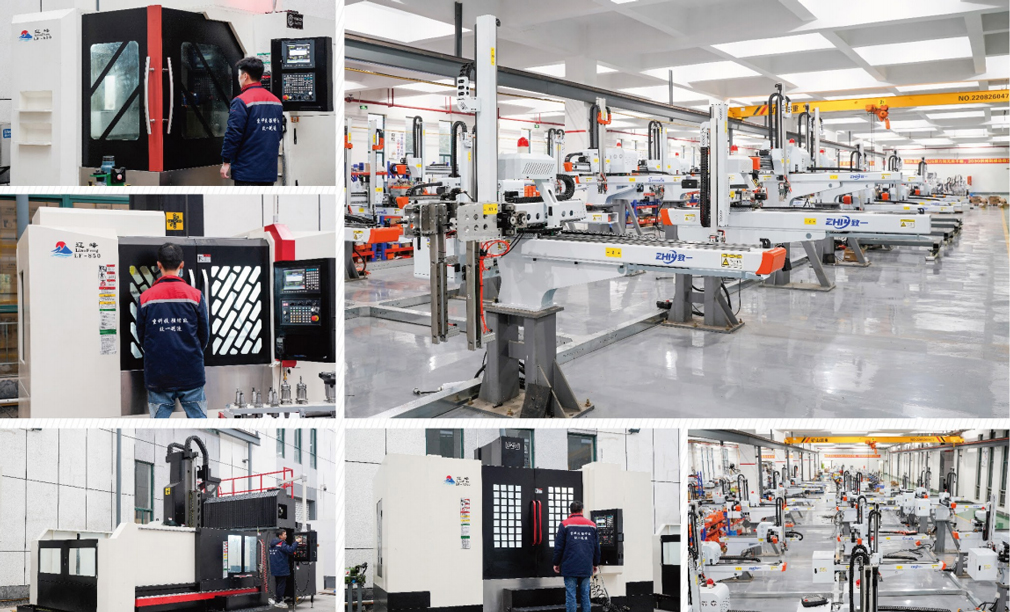
Based on practical standards in the global injection molding industry, the following formulas have been verified through over a thousand project cases (referencing ZHIYI Intelligent's 500+ project implementation experience), and are applicable to mainstream 3-axis and 5-axis servo robot arm selection.
1. Horizontal Travel (X-axis) Matching Formula
Horizontal Travel = Maximum Mold Width (W) + Safety Distance (S1) + Product Placement Offset (L)
Maximum Mold Width (W): The maximum lateral dimension from the fixed mold plate to the moving mold plate of the injection molding machine (can be found in the injection molding machine parameter table);
Safety Distance (S1): The reserved space to avoid interference between the robot arm and the mold and the injection molding machine body, typically 50-100mm (the larger the mold size, the larger the value);
Product Placement Offset (L): The lateral distance of the product placed on the conveyor belt/container after removal, typically 100-300mm (adjusted according to the production line layout).
Example: A 50-ton injection molding machine with a maximum mold width of 400mm, a safety distance of 80mm, and a product placement offset of 200mm, then the horizontal travel = 400+80+200=680mm. A servo robot arm with a 700mm horizontal travel is recommended.
2. Vertical Stroke (Z-axis) Matching Formula
Vertical Stroke = Maximum Injection Molding Machine Opening/Closing Stroke (H) + Product Height (h) + Safety Distance (S2) + Part Removal Height Offset (H1)
Maximum Injection Molding Machine Opening/Closing Stroke (H): The maximum lifting distance of the injection molding machine's moving platen (a core parameter, which should be based on the parameter table provided by the injection molding machine manufacturer);
Product Height (h): The maximum height of the molded product (including gate and runner height);
Safety Distance (S2): Reserved clearance in the vertical direction to prevent the robot arm from colliding with the mold top/bottom plate, typically 30-80mm;
Part Removal Height Offset (H1): The height the product rises after being removed (must be higher than the mold top plate for easy horizontal movement), typically 50-150mm.
Example: For a 100-ton injection molding machine with a maximum opening/closing stroke of 350mm, product height of 50mm, safety distance of 50mm, and part removal height offset of 100mm, the vertical stroke = 350+50+50+100=550mm. A servo robot arm with a 600mm vertical stroke is recommended.
3. Forward/Backward Stroke (Y-axis) Matching Formula
Forward/Backward Stroke = Maximum Mold Depth (D) + Injection Molding Machine Platen Thickness (T) + Safety Distance (S3)
Maximum Mold Depth (D): The maximum longitudinal dimension of the mold from the parting line to the back plate;
Injection Molding Machine Platen Thickness (T): The thickness of the injection molding machine's moving/fixed platen (can be found in the injection molding machine parameter table);
Safety Distance (S3): Reserved clearance in the forward/backward direction to prevent the robot arm from interfering with the injection molding machine nozzle and barrel, typically 50-100mm.
Example: For a 200-ton injection molding machine with a maximum mold depth of 300mm, platen thickness of 200mm, and safety distance of 80mm, the forward/backward stroke = 300+200+80=580mm. A servo robot arm with a 600mm forward/backward stroke is recommended.
IV. Reference Table for Robot Arm Stroke Selection for Different Tonnage Injection Molding Machines
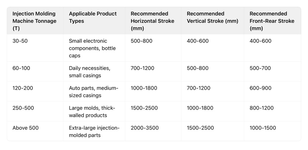
Note: The above are general reference values. Actual selection needs to be adjusted based on mold size, production line layout, and picking method (single arm/double arm). It is recommended to consult a professional technical team for calculations.
V. Three Key Steps for Matching Calculation (Purchaser's Practical Guide)
Collect core parameters: Obtain "tonnage, maximum mold opening/closing stroke, and platen thickness" from the injection molding machine manufacturer, and "maximum mold width/depth/height" from the mold manufacturer. Clearly define product dimensions and production line layout (product placement position);
Calculate using formulas: Calculate each item according to the horizontal, vertical, and front-to-back stroke formulas above. The safety distance needs to be adjusted according to the actual workshop environment (e.g., it can be appropriately reduced if the workshop space is small, but not less than 30mm);
Reserve redundancy: Add 5%-10% redundancy to the calculation results to cope with scenarios such as mold changes and product iterations (e.g., if the calculated horizontal stroke is 680mm, selecting 700-750mm is more reliable).
VI. Common Matching Mistakes and Avoidance Methods
Mistake 1: Only considering tonnage, ignoring mold size
Injection molding machines of the same tonnage can be matched with different sized molds (e.g., a 100-ton injection molding machine can be matched with 300mm or 500mm wide molds). Directly selecting based on tonnage can easily lead to insufficient stroke.
Avoidance: Use the actual mold size as the core parameter, and use tonnage only as an auxiliary reference.
Mistake 2: Taking too small a safety distance
Selecting the minimum stroke to save costs, ignoring factors such as workshop dust and equipment vibration, can easily lead to collisions.
Avoidance: Reserve 50-100mm for conventional scenarios, and 100-150mm for high-precision production or complex molds.
Mistake 3: The larger the stroke, the better
Excessive stroke will increase the robot arm's movement time (each additional 500mm of stroke increases the single picking time by 0.3-0.5 seconds), reducing the production cycle.
Avoidance: Calculate precisely according to the formula, and only reserve the necessary redundancy. Misconception 4: Neglecting Servo Robot Accuracy Parameters
While matching the stroke length, it's crucial to ensure the robot's repeatability (recommended within ±0.1mm) to avoid affecting picking stability.
Avoidance: Prioritize selecting servo robots with ISO9001 and CE certifications (such as ZHIYI series products) during selection to ensure accuracy and stability.
VII. Additional Considerations for Servo Robot Selection
Load and Stroke Coordination: The larger the stroke, the greater the load capacity required for the robot (e.g., a 2000mm horizontal stroke requires a load capacity of ≥10kg) to prevent shaking during movement;
Multi-axis Coordination Requirements: Complex injection molding scenarios (such as insert molding and multi-station picking) require a 5-axis dual-arm servo robot. Interference between the two arms must be considered when matching the stroke;
Customized Solutions: For special molds (such as core-pulling molds, two-color molds) or non-standard production lines, a professional team is needed to provide customized stroke design (ZHIYI can provide on-site survey and solution design services);
After-sales and Technical Support: Choose a manufacturer that provides 24-hour technical support to avoid production line downtime due to matching problems.
Conclusion: Scientific Matching is the Core Prerequisite for Automation Upgrades
The precise matching of injection molding machine tonnage and robot stroke is the foundation for achieving "efficient, stable, and safe" automated production. Using the above formulas and selection guidelines, purchasers can initially complete the selection calculations, but for complex scenarios (such as multi-mold switching, high-precision production), it is recommended to consult a professional technical team.