Leave Your Message
How to Ensure Stable Hydraulic System Operation in a Three-Axis Servo Robot?
How to Ensure Stable Hydraulic System Operation in a Three-Axis Servo Robot?
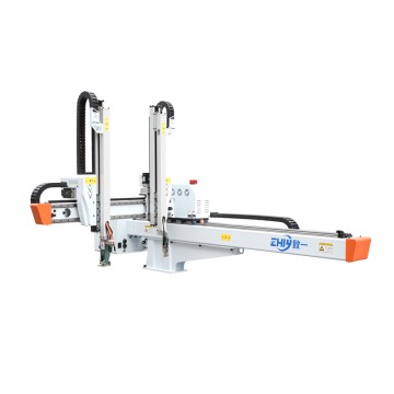
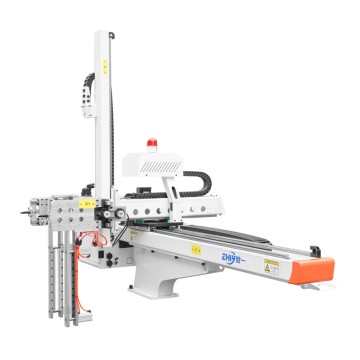
In automated production, three-axis servo robots, with their high precision and responsiveness, have become essential equipment for stamping, assembly, and handling applications. The hydraulic system, the "heart" of the robot's power transmission, directly determines its stability, positioning accuracy, operating efficiency, and equipment lifespan. Pressure fluctuations, leaks, and seizures in the hydraulic system can not only disrupt production but also potentially lead to safety incidents such as scrapped workpieces and equipment damage. This article will examine the core components of the hydraulic system, deeply analyzing the key factors affecting stability and providing a comprehensive solution from design and selection to ongoing maintenance, helping companies achieve long-term, stable hydraulic system operation.

First, Understand the "Heart":
The Core Components and Stability Requirements of the Three-Axis Servo Robot's Hydraulic System
To ensure hydraulic system stability, it's important to first understand its core components and their specific roles within the three-axis servo robot. Unlike conventional hydraulic systems, the hydraulic system of a three-axis Servo Manipulator requires close coordination with the servo motor and PLC control system to meet the stringent requirements of "high-frequency start-stop, precise speed regulation, and instantaneous pressure response." Its core components and stability requirements can be summarized in the following three points:
1. The Core Components' Role as a "Stabilizing Foundation"
The hydraulic system of a three-axis servo manipulator primarily consists of five components: the power element (servo hydraulic pump), actuators (hydraulic cylinders/motor), control elements (proportional valves, servo valves), auxiliary components (oil tank, filter, cooler), and hydraulic oil.
Servo hydraulic pump: As the power source, its output flow must precisely match the servo motor speed, directly impacting system pressure stability.
Proportional/ Servo valves: Control the flow and direction of hydraulic oil, determining the motion accuracy of each axis of the robot. Even the slightest sticking of the valve core can cause positioning error.
Hydraulic cylinders: Convert hydraulic energy into mechanical energy. Their sealing performance and cylinder barrel accuracy are directly related to smooth operation.
Auxiliary components: Filters trap impurities, coolers control oil temperature, and oil tanks store oil, dissipate heat, and deposit impurities, providing the "logistical support" for system stability.
2. Special Stability Requirements for Hydraulic Systems in Robots
Compared to fixed hydraulic equipment, the hydraulic system of a three-axis servo Robot Must meet three core requirements:
No Pressure Fluctuation: When the robot grasps and moves workpieces, the system pressure must remain constant (error ≤ ±0.2 MPa). Otherwise, workpieces may fall off or positioning errors may occur.
Matched Response Speed: The hydraulic system's flow output must be synchronized with the servo motor's speed changes, with a lag time of less than 50ms to ensure precise movement.
No Longer-Term Leakage: Since robots often operate in cleanrooms, hydraulic oil leaks could not only contaminate the workpiece but also cause a sudden drop in system pressure, potentially leading to safety incidents.
Second, Tracing the Root Cause:
Six Core Factors Affecting the Stability of a Three-Axis Servo Manipulator's Hydraulic System
Hydraulic system instability is often the result of a combination of multiple factors. Based on actual operation and maintenance experience, the core influencing factors can be summarized into the following six categories, which require special attention:
1. Hydraulic Oil: Deterioration of the "blood" is the "invisible killer" of stability.
Hydraulic oil is the medium that transmits power, and its performance degradation is the primary cause of system failure:
Excessive contamination: Airborne dust, metal wear debris (such as from pump shaft and valve core wear), and moisture (seeping through the tank breather port) can cause hydraulic oil contamination to exceed the standard (NAS level 8 or above), causing valve core sticking and filter clogging, which in turn causes pressure fluctuations.
Abnormal viscosity: When the ambient temperature is too low, the hydraulic oil viscosity increases, the fluidity deteriorates, and the system response is delayed. Excessive temperature (exceeding 100°C) can cause the hydraulic oil to become contaminated beyond the standard (NAS level 8 or above). 60°C) will reduce viscosity and oil film strength, exacerbating wear on pumps and valves and accelerating oil oxidation and deterioration.
Additive deterioration: Anti-wear agents, antioxidants, and other additives in hydraulic oil gradually deplete over time, reducing the oil's wear resistance and causing premature wear of pump bodies and cylinder barrels.
2. Servo Hydraulic Pump: Power Source Failure Directly Leads to "Insufficient Power"
The servo hydraulic pump is the "power heart" of the system, and its failures account for over 30% of all hydraulic system failures:
Pump Wear: After long-term operation, the gap between the pump's rotor and stator increases, leading to increased internal leakage, decreased output flow, and inability to maintain stable system pressure.
Variable Mechanism Seizure: Impurities can become stuck in the servo pump's variable piston, preventing it from adjusting flow according to load demand. This results in "insufficient flow under high loads and excessive flow under low loads," causing pressure fluctuations.
Motor-Pump Coaxiality Deviation: When the servo motor and hydraulic pump are installed with a coaxiality exceeding 0.1mm, radial forces are generated, exacerbating pump shaft wear and increasing vibration and noise, indirectly affecting system stability.
3. Control Components: Valve Failure is the Main Cause of "Precision Loss"
Control components such as proportional valves and servo valves directly determine motion accuracy, and their failures can easily lead to "inaccurate" robot movements:
Valve Spool Wear and Sticking: Impurities in the hydraulic oil can scratch the valve spool or valve sleeve, increasing clearance and internal leakage. Valve Spool Sticking can prevent precise control of the valve opening, causing flow fluctuations.
Solenoid Performance Degradation: After the proportional valve's solenoid is energized for a long time, the coil ages, resulting in reduced suction, slower valve spool response, and mismatched signals with the servo control system.
Valve Port Blockage: Tiny impurities blocking the valve port can cause nonlinear flow control, manifesting as "stuttering" or "creeping" robot movements.
4. Sealing System: Leakage is the Direct Cause of "Pressure Loss"
Seal failure not only wastes hydraulic fluid but also directly disrupts system pressure balance:
Seal aging: Nitrile rubber seals are prone to hardening and cracking in high-temperature, oil-immersion environments, losing their sealing ability;
Improper installation: Scratches on seals during assembly, as well as insufficient or excessive compression, can lead to seal failure;
Cylinder/piston rod damage: Scratches on the inner wall of the hydraulic cylinder barrel and peeling of the piston rod coating can exacerbate seal wear, creating a vicious cycle of "more wear, more leaks, more leaks, more wear."
5. Oil Temperature Control: Temperature Imbalance Catalyzes Premature System Aging
Oil temperature is the "body temperature" of the hydraulic system. Normal operating temperature should be maintained between 35-55°C. Exceeding this range can lead to a series of problems:
Excessive oil temperature accelerates hydraulic oil oxidation (every 15°C increase in temperature reduces oil life by half), causing seal degradation and reducing the volumetric efficiency of the hydraulic pump.
Excessive oil temperature increases oil viscosity, increasing flow resistance and making cavitation more likely during system startup. This can lead to pump cavitation, vibration, and noise.
6. System Design: Inherent Defects Lay Hidden "Instability Hidden Dangers"
The instability of some hydraulic systems stems from inherent flaws during the design phase:
Improper circuit design: For example, the relief valve is too far from the pump, preventing timely buffering of pressure surges; improper throttle valve selection results in a flow adjustment range that cannot match the robot load changes;
Fuel tank design flaws: The tank volume is too small (generally 3-5 times the system flow), resulting in insufficient heat dissipation area; the lack of baffles within the tank allows return and suction oil to mix, preventing effective separation of bubbles in the oil;
Complex piping layout: Pipe bend radii are too small, resulting in excessive localized pressure loss; high-pressure and low-pressure lines run in parallel, interfering with each other and causing vibration.
Third, System Solution:
From Design to Operation and Maintenance, Seven Key Measures to Ensure Stable Hydraulic System Operation
To address the aforementioned influencing factors, a comprehensive process management and control system must be established, encompassing "design optimization - selection control - standardized installation - precise commissioning - effective operation and maintenance - monitoring and early warning - and rapid troubleshooting." Specific measures are as follows:
1. Design Optimization: Laying a Solid Foundation for Stability
During the design phase, the hydraulic system solution must be optimized based on the load characteristics and motion trajectory of the three-axis servo manipulator:
Circuit Design: Utilize a dual-control system of "servo pump + proportional valve." The servo pump regulates high flow, while the proportional valve controls precise flow to minimize pressure fluctuations. An accumulator is added to the pump outlet to mitigate pressure surges during startup. A cooler is installed in the return oil line to ensure stable oil temperature.
Oil Tank Design: The tank capacity is 4 times the system's maximum flow. The design features internal partitions for the oil suction, return, and settling areas. A splash guard is installed at the oil return port, and the oil suction port is located ≥150mm from the bottom of the tank to prevent the ingestion of settled impurities. A breather cap with a desiccant is installed on the top of the tank to prevent moisture ingress.
Pipeline Layout: High-pressure piping (pressure ≥16MPa) utilizes seamless steel pipe with a bend radius ≥10 times the pipe diameter. Low-pressure piping utilizes nylon tubing to prevent interference with the robot's moving parts. Vibration-absorbing pipe clamps are used to secure the pipes to minimize vibration transmission.
2. Accurate Selection: Choose "Compatible" Core Components
Component selection should adhere to the principles of "matching the load, providing redundancy, and ensuring reliable quality":
Servo Hydraulic Pump: Calculate the required maximum flow and pressure based on the manipulator's maximum load and movement speed. When selecting a pump, allow a 20% margin for flow. Variable displacement piston pumps are preferred, as they offer high volumetric efficiency (≥90%) and fast flow regulation response.
Control Components: Proportional valves and servo valves should be selected with a diameter that matches the flow rate. Their rated pressure should be 30% higher than the system operating pressure. Electro-hydraulic servo valves with spool position feedback are preferred, offering control accuracy of ±0.5%.
Seals: Select the appropriate sealing material based on the hydraulic oil type and operating temperature (e.g., fluororubber for high-temperature environments and nitrile rubber for low-temperature environments). Control seal compression within 20%-30% to ensure effective sealing while preventing excessive wear.
Hydraulic Oil: Anti-wear hydraulic oil (e.g., L-HM46), with a viscosity index ≥140 and strong oxidation resistance. For low-temperature environments, L-HV46 low-temperature anti-wear hydraulic oil can be used to ensure low-temperature fluidity.
3. Standard Installation: Avoiding "Acquired Installation Defects"
Installation quality directly impacts system stability and must strictly adhere to the following standards:
Motor-Pump Coaxiality Adjustment: Use a dial indicator to ensure the coaxiality deviation between the motor shaft and the pump shaft is ≤0.05mm, and the parallelism deviation is ≤0.1mm/m.
Pipe Installation: Pipeline welding is performed using argon arc welding. After welding, perform pickling and passivation to remove weld slag and scale. Before assembly, purge the pipes with compressed air to ensure they are free of impurities. Tighten fittings using a torque wrench to the rated torque (e.g., for an M20 fitting, the torque is ≤0.05mm). 50-60N·m);
Hydraulic Cylinder Installation: The hydraulic cylinder and manipulator joints are connected using floating joints to compensate for installation errors. A dust cover must be installed on the extended end of the piston rod to prevent dust from entering the cylinder.
Filter Installation: The suction filter must be installed at the tank intake port, with a filtration accuracy of ≥100μm. The high-pressure filter must be installed at the pump outlet, with a filtration accuracy of ≥10μm. The return oil filter must be installed in the return oil line, with a filtration accuracy of ≥20μm and a clogging alarm.
4. Fine Tuning: Achieving Precise Matching of Human-Machine Collaboration
Tuning is a critical step in ensuring the coordinated operation of the hydraulic system and servo control system:
Pressure Tuning: After starting the system, gradually adjust the relief valve to bring the system pressure to the designed value (e.g., 12 MPa). Maintain the pressure for 30 minutes and observe a pressure drop of ≤0.1 MPa. Test the system pressure with the Robot Both unloaded and fully loaded to ensure no significant pressure fluctuations.
Flow Tuning: Send control signals of varying frequencies through the PLC to adjust the proportional valve opening, measure the corresponding flow output, and plot a "signal-flow" curve to ensure linearity of ≥95%.
Coordinated Tuning: Debug the hydraulic system in conjunction with the servo motor and PLC control system. Test the motion accuracy (e.g., positioning error ≤±0.02mm) and response speed (e.g., time from standstill to rated speed ≤0.5s) of each axis of the robot to ensure synchronized responses between the hydraulic and electrical systems.
5. Scientific Operation and Maintenance: Establish a "Regular + On-demand" Maintenance System
Daily maintenance is key to extending the life of hydraulic systems and ensuring stability. A standardized maintenance process should be established:
Hydraulic Oil Maintenance: For new systems, replace the hydraulic oil after 100 hours of operation, and every 2,000 hours thereafter. Test the oil monthly for contamination (NAS grade 8 or below is acceptable), viscosity (viscosity deviation ≤ ±10% at 40°C), and moisture content (≤0.1%). Filter the oil (filtration accuracy ≥ 10μm) when replenishing it, ensuring it matches the original brand.
Filter Maintenance: Clean the suction filter every three months, and replace the high-pressure and return filters every six months. If the clogging alarm is triggered, replace them immediately.
Seal Maintenance: Inspect the seals of hydraulic cylinders and valves every year. Replace any leaks or deterioration immediately. When replacing seals, clean the mounting surfaces to prevent contamination.
Servo Pump Maintenance: Clean the seals every 3,000 days. Check the pump body for wear every hour and measure the clearance between the rotor and stator (replace if it exceeds 0.1mm). Replace the pump lubricant every year and check the fluidity of the variable speed mechanism.
Oil temperature control: Ensure the cooler operates properly. If the ambient temperature is too high in summer, add a fan or air conditioner to reduce the temperature. In winter, preheat the oil to above 20°C before starting the machine using a heater.
6. Real-time Monitoring: Establishing an "Early Warning" Mechanism
Leveraging IoT technology, we enable real-time monitoring of hydraulic systems to proactively detect potential faults:
Key Parameter Monitoring: Pressure sensors, flow sensors, and temperature sensors collect real-time system pressure, flow, and oil temperature data, enabling the establishment of alarm thresholds (e.g., alarms for pressure fluctuations of ±0.3 MPa and oil temperatures ≥60°C).
Vibration and Noise Monitoring: Vibration sensors are installed near the servo pump and hydraulic cylinder to monitor vibration acceleration (normally ≤10 m/s²). Abnormal vibration or noise may indicate pump wear or valve core sticking.
Leakage Monitoring: Oil leak sensors are installed below the oil tank, and leak detection tape is applied to key joints. Immediate alarms are activated upon detection of leaks to prevent further damage.
7. Quick Troubleshooting: Establish a "Precise Positioning - Efficient Handling" Maintenance Process
When a hydraulic system malfunction occurs, follow the principle of "easy first, difficult later, external first, internal later" to quickly troubleshoot and resolve it:
Pressure Fluctuation: First check the hydraulic oil contamination and viscosity. If normal, check the servo pump's variable displacement mechanism for sticking, and then check the proportional valve spool for wear.
Insufficient Flow: First check the filter for blockage, then measure the pump's output flow. If insufficient, replace the servo pump.
Leakage: First check for loose joints, then check for seals for deterioration, and finally check the cylinder and piston rod for damage.
Stuck Movement: First check for excessive hydraulic oil viscosity, then check for malfunctioning proportional valve solenoids, and finally check for sticking hydraulic cylinders.
Fourth, Case Study:
Improving Hydraulic System Stability at an Auto Parts Factory
A three-axis servo robot at an auto parts factory was experiencing frequent issues with large pressure fluctuations (up to ±0.5 MPa) and positioning errors exceeding ±0.1 mm when gripping workpieces during its stamping production line. This resulted in a 15% drop in production efficiency. After implementing the following optimization measures, system stability was significantly improved:
Cause Diagnosis: Testing revealed hydraulic oil contamination reaching NAS level 10, a clearance of 0.15mm between the servo pump rotor and stator, scratches on the proportional valve spool, and a reservoir capacity only twice the system flow rate. Inadequate heat dissipation caused the oil temperature to frequently exceed 65°C.
Optimization Measures:
Replaced L-HM46 hydraulic oil, cleaned the reservoir, and installed baffles and a cooler.
Replaced the servo pump and proportional valve, and adjusted the motor-pump coaxiality to 0.03mm.
Installed pressure, temperature, and vibration sensors, connected to the factory's MES system, and set real-time alarm thresholds.
Established an operational maintenance process of "monthly oil testing, quarterly filter replacement, and semi-annual seal inspection."
Optimization Results: System pressure fluctuations were controlled within ±0.1MPa, positioning errors were ≤±0.02mm, and downtime was reduced from 8 hours per month to less than 0.5 hours, increasing production efficiency by 20%.
Fifth, Summary: The Core of Stable Operation is "Full Lifecycle Management"
Stable operation of a three-axis servo robot's hydraulic system cannot be achieved through optimization of a single step; rather, it requires comprehensive management throughout its entire lifecycle, from design and selection to installation, commissioning, operation, maintenance, and monitoring. The key lies in: ensuring compatibility between components and the robot's load and motion characteristics; prioritizing preventive maintenance through oil management and regular inspections; and supporting intelligent monitoring, leveraging sensors and data-driven methods to provide accurate early warnings. Only by establishing a systematic and standardized management and control system can the hydraulic system truly become the "reliable heart" of the three-axis servo robot, providing continuous and stable power for automated production.