Leave Your Message


A Complete Guide to Daily Maintenance of Injection Molding Machine Servo Robots
A Complete Guide to Daily Maintenance of Injection Molding Machine Servo Robots: 6 Core Steps to Extend Equipment Life by 30%
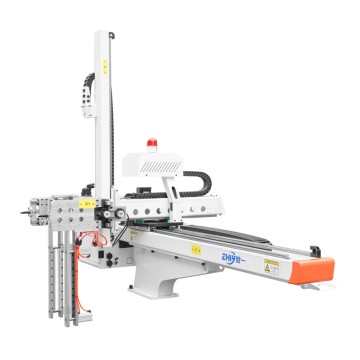
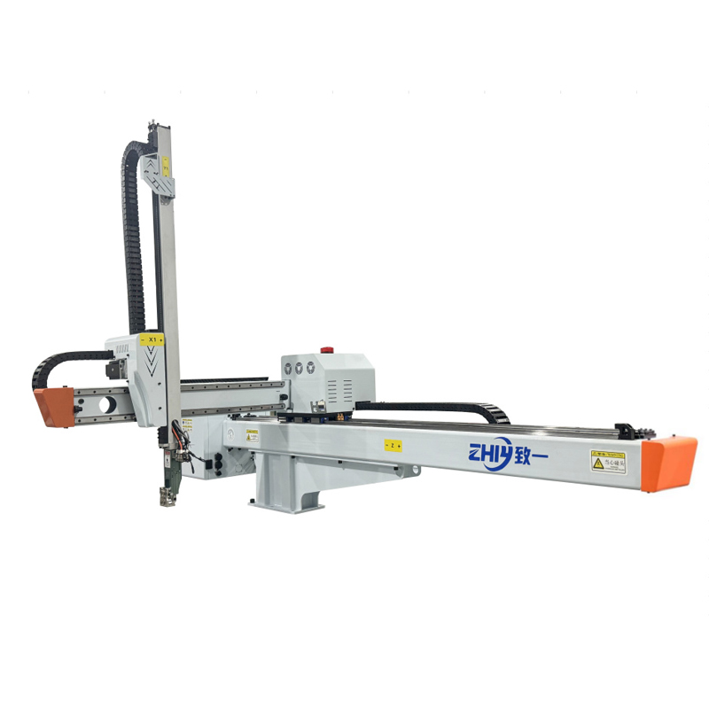
In injection molding production lines, servo robots serve as the "heart of automation." Their operational stability directly determines production efficiency, product quality, and equipment maintenance costs. According to industry statistics, standardized daily maintenance can reduce the failure rate of injection molding machine servo robots by over 40% and extend their service life by 30%. However, neglecting maintenance can lead to serious problems such as robot jamming, positioning deviation, and servo motor burnout, resulting in an average daily production loss of tens of thousands of yuan. This article systematically explains the daily maintenance steps for injection molding machine servo robots, from basic inspections to in-depth maintenance, providing practitioners with practical and achievable guidance.
I. Pre-Maintenance Preparation: Ensure Safety and Tools
Safety is always paramount before beginning any maintenance operation. The servo robot for an injection molding machine is a high-precision mechatronic device. Improper operation can cause mechanical pinching, electrical short circuits, and other risks. Therefore, the following preparations are essential:
Equipment Shutdown and Power Off: Turn off the robot's main power switch and disconnect the signal control cable to the injection molding machine to ensure the robot is completely de-energized. If the robot is equipped with an emergency stop button, press it and lock it to prevent accidental activation.
Safety Warning and Isolation: Place a "Maintenance in Progress, No Operation" warning sign around the robot. Use safety fencing or warning tape to isolate the work area and prohibit non-maintenance personnel from approaching.
Tool and Consumables: Prepare specialized tools according to the maintenance checklist, including an Allen wrench (set), Phillips/slotted screwdrivers, a torque wrench, a grease gun, a dust-free cloth, alcohol, rust inhibitor, and lubricant (prepare the type specified in the equipment manual, such as lithium-based grease or gear oil). Also prepare a maintenance log to record inspection results.
Data Verification: Retrieve the robot's Operation Manual and Maintenance Instructions to confirm the maintenance parameters for each component (such as bolt torque, lubrication intervals, and oil type) to avoid improper maintenance due to incorrect parameters.
II. Mechanical Structure Maintenance: "Basic Maintenance" of Core Components
The mechanical structure is the vehicle for the robot's precise movements and includes components such as the arm, joints, guides, and suction cups. Daily maintenance should focus on four key areas: cleaning, lubrication, tightening, and wear inspection.
1. Arm and Joints: Preventing Jams and Noise
Cleaning: Use a dust-free cloth dampened with a small amount of alcohol to wipe away plastic debris, oil, and dust from the arm's surface. Focus on cleaning the joint joints, as these areas are prone to accumulation of impurities and can hinder rotation.
Lubrication: Fill the joint bearings with the specified type of grease (such as high-temperature lithium-based grease) as directed in the manual. When using a grease gun, slowly inject until the grease evenly flows out of the bearing gaps (avoid excessive grease contamination). If the joint is equipped with a lubrication oil circuit, check the circuit for unobstructed flow and refill the lubricant to the specified level.
Tightening and Inspection: Use a torque wrench to check the bolts and nuts at the joint for looseness (tighten to the torque specified in the manual, e.g., 25-30 N·m for M8 bolts). Observe the joint for any unusual noises, sticking, or looseness during rotation. If bearing wear or excessive clearance is observed, replace the spare parts promptly.
2. Guide Rails and Sliders: Ensuring Operational Accuracy
Cleaning: The guide rails are the core of the robot's linear motion. Use a brush to remove iron filings and plastic particles from the guide rail surface. Then, use a lint-free cloth dampened with a guide rail cleaner to wipe away any old lubricant and dirt from the guide rail and slide surfaces. Lubrication: Apply guide rail oil evenly along the length of the guide rail (we recommend using anti-wear guide rail oil with moderate viscosity, such as 32# or 46#). After application, manually move the slider back and forth 2-3 times to ensure that the lubricant evenly covers the guide rail contact surface. If the system uses an automatic lubrication system, check the oil level and pressure of the lubrication pump and whether the set lubrication interval (e.g., lubrication once every hour of operation) meets the requirements.
Wear Inspection: Inspect the guide rail surface for scratches, pits, or rust. Use a feeler gauge to measure the clearance between the slider and the guide rail. If the clearance exceeds 0.1mm, it may cause positioning deviation of the robot and require replacement of the slider or guide rail. 3. End Effectors: "Critical Touchpoints" for Adapting to Production Needs
End effectors (such as suction cups and grippers) come into direct contact with injection molded products, requiring specific maintenance based on their type:
Suction cups: Inspect the cups for damage and aging (e.g., surface cracks or decreased elasticity). If suction is insufficient, clean the dust and oil inside the cups or replace them with new ones. Also, check the vacuum lines for leaks (this can be determined by blocking the suction cup opening, starting the vacuum pump, and observing whether the vacuum gauge reading is stable). Tighten the pipe joints and replace any worn seals.
Grippers: Clean any plastic residue from the gripper surfaces and inspect the teeth for wear (if the gripper slips when gripping the product, this may be due to wear). Apply a small amount of lubricant to the gripper's drive cylinder rod and inspect the cylinder for leaks and smooth movement.
III. Electrical System Maintenance: Avoid Short Circuits and Signal Failures
The electrical system of an injection molding machine's servo robot, including the control cabinet, servo motors, sensors, and cables, is the "nerve center" of the equipment. Maintenance should focus on insulation, connections, and heat dissipation to prevent electrical failures from causing downtime:
1. Control Cabinet: Keep it dry and ventilated
Cleaning and Dust Removal: After powering off, open the control cabinet door and use a hair dryer (on cold air mode) or a brush to remove dust inside the cabinet. (Please focus on dust accumulation on the contactors, relays, and inverters to prevent short circuits or poor heat dissipation.) Wipe the touch screen and button panel on the inside of the cabinet door with a dust-free cloth to keep the interface clear.
Wiring Inspection: Check all wiring terminals for loose connections (tighten each one with a screwdriver). Observe the wire insulation for signs of aging or damage (e.g., yellowing or cracking). If any wires are worn, wrap them with insulating tape or replace them. Also, check that the grounding circuit is reliable (the grounding resistance should be less than 4Ω) to prevent static electricity or leakage from causing equipment failure. Heat dissipation inspection: The cooling fan and heat sink inside the control cabinet are key. Clean the fan surface to ensure proper operation (if the fan makes unusual noises or stops, replace it immediately). Check the heat sink for blockage. If the ambient temperature is high (e.g., in an injection molding workshop exceeding 35°C), install auxiliary cooling equipment (such as industrial air conditioning).
2. Servo Motor: Core Power "Health Monitoring"
Appearance and Temperature: Inspect the servo motor surface for oil and dust, and inspect the motor casing for deformation or cracks. Before operation, touch the motor casing to check for normal temperature (normal operation generally does not exceed 60°C. If it is too hot, it may be due to overload, bearing damage, or poor heat dissipation).
Wiring and Insulation: Check the motor power and encoder wiring for tight connections and encoder cable damage. Check the encoder cable for any damage (the encoder signal directly affects positioning accuracy, and cable damage can cause the robot to misalign). Use a multimeter to measure the insulation resistance of the motor windings (phase-to-phase insulation resistance should be greater than 10MΩ) to prevent short circuits that could damage the motor. Abnormal Noise and Vibration: Start the robot and listen for any unusual noises (such as buzzing or squeaking) from the servo motor during operation. Measure the motor's vibration with a vibration meter (usually with an amplitude of less than 0.05mm). Excessive vibration may indicate worn motor bearings or an unbalanced rotor, requiring disassembly and repair.
3. Sensors and Switches: Ensure Signal Accuracy
Position Sensors (such as photoelectric sensors and proximity switches): Clean the sensor head (to prevent dust from obstructing the sensor and causing signal misinterpretation). Check the sensor's mounting position for offset (a tape measure can be used for calibration). Use a multimeter to test the sensor's output signal (for example, an NPN sensor outputs a high level when not sensing and a low level when sensing) to ensure signal stability.
Limit Switches: The robot's travel limit switches (such as the origin switch and extreme position switches) are critical for safety. Manually trigger the switch to verify that it is properly shutting off the actuation signal (if the limit switch is triggered, the Robot Should immediately stop). If the switch malfunctions, replace the contacts or the entire switch.
IV. Servo System Maintenance: The Core Guarantee of Precision Control
The servo system (including the servo drive, encoder, and servo motor) determines the robot's motion accuracy and response speed. Maintenance should focus on the stability of its parameters, status, and heat dissipation:
1. Servo Drive: Double-check Parameters and Status
Parameter Check: Use the drive's operation panel or debugging software connected to a computer to verify that servo parameters (such as position loop gain, velocity loop gain, torque limit, etc.) are consistent with the factory settings. Incorrect parameter modifications may cause unstable Robot Movement (such as jitter and overshoot). If the parameters are abnormal, restore the factory settings and re-debug.
Status Monitoring: After starting the drive, observe the status code displayed on the panel to ensure it is normal (e.g., "00" for standby, "01" for operation). If a fault code appears (e.g., "E02" for overcurrent, "E05" for encoder failure), refer to the manual to identify the cause. (For example, overcurrent may indicate a motor short circuit or excessive load, while an encoder failure may indicate poor cable contact).
Heat dissipation maintenance: Servo drives generate significant heat during operation. Clean the heat dissipation holes and fins on the drive surface to ensure unobstructed heat dissipation. Check the drive's fan for proper operation. If the fan malfunctions, replace it immediately to prevent the drive from tripping due to overheating.
2. Encoder: Calibration is key to positioning accuracy
Cleaning and connection: The encoder is the core of the robot's positioning and navigation. Check that the encoder housing is properly sealed to prevent dust and oil from entering. Clean the encoder's signal cable connector and reconnect it to ensure reliable contact. Loose signal cables are a common cause of positioning errors.
Zero point calibration: If the robot experiences positioning inaccuracies (such as offset gripping positions), perform encoder zero point calibration. Manually move the robot to the "mechanical origin" position and perform a "zero reset" operation using the drive panel or debugging software. Repeat the calibration test 3-5 times to ensure that the positioning error is within the allowable range (usually within ±0.02mm).

V.Pneumatic System Maintenance: The "Stable Foundation" of Power Transmission
The end effectors and auxiliary movements (such as hopper opening and closing) of most injection molding machine servo robots rely on pneumatic systems. Maintenance should focus on ensuring a clean air source, intact components, and unobstructed piping.
1. Air Processing Unit: Ensure filtration, pressure regulation, and lubrication are in place.
Air Filter: Open the filter drain valve to drain condensate (recommended 1-2 times daily, more frequently in humid environments). Regularly (e.g., weekly) remove the filter element and backflush it with compressed air (clogging can lead to insufficient air flow). If the filter element is damaged, replace it with a new one (5μm filter is recommended to filter out impurities).
Pressure Reducing Valve: Check the output pressure of the pressure reducing valve for stability (typically set to 0.4-0.6 MPa, adjusted according to actuator requirements). If the pressure fluctuates excessively, disassemble the valve core for cleaning and apply a small amount of pneumatic grease. Also, check the pressure gauge for accuracy. If the gauge is stuck, replace the gauge. Lubricator: Check the oil level in the lubricator (add pneumatic lubricant, such as ISO VG32) and adjust the oil mist volume (typically set to 1-2 drops of oil per 1000L of air). Insufficient oil mist can cause wear on the cylinder and solenoid valve, while excessive oil can cause oil contamination.
2. Cylinder and Solenoid Valve: "Guaranteeing Smooth Operation"
Cylinder: Check the cylinder body for leaks (apply soapy water to the piston rod and cylinder head and observe for bubbles). Check the piston rod surface for scratches and rust (if any, sand it with fine sandpaper and apply rust inhibitor).
VI.Add a small amount of lubricant to the connection between the piston rod and cylinder head to ensure smooth and unobstructed cylinder extension and extension.
Solenoid Valve: Clean dust from the solenoid valve surface, check the solenoid valve wiring for security, and manually activate the solenoid valve's manual button to observe whether the valve core moves smoothly. If the valve core moves slowly, it may be stuck and require disassembly, cleaning, or replacement of the solenoid valve. Post-Maintenance Testing and Recording: Closed-Loop Management to Prevent Omissions
After completing the above maintenance steps, a closed-loop process (no-load test → load test → parameter recording) is required to ensure the robot has returned to normal operation:
No-load Test: Connect the power, release the emergency stop, and manually operate the robot to perform basic movements such as lifting, retracting, and rotating. Observe whether all components operate smoothly and whether there are any abnormal noises. Check the positioning accuracy of the servo system (e.g., whether the repeatability error is within the standard range) and the pressure stability of the pneumatic system.
Load Test: Install an injection molded product to simulate actual production scenarios and run the robot for 10-20 consecutive cycles. Check the gripping stability of the end effector (e.g., whether the suction cup is leaking or the gripper is slipping). Observe the current and temperature during operation to ensure they are normal (the servo motor current should not exceed 80% of the rated current). Maintenance Records: Complete the "Injection Molding Machine Servo Robot Maintenance Record Form," detailing maintenance dates, maintenance items, replaced parts (such as suction cups, filter elements, and grease types), test data (such as positioning error and motor temperature), any issues discovered, and their resolution. This will facilitate follow-up and regular maintenance planning.
VII. Maintenance Cycles and Common Misconceptions
1. Scientifically Plan Maintenance Cycles
Daily Maintenance: Clean the arm and end effector, check the air filter drain, and test the robot's no-load operation.
Weekly Maintenance: Lubricate the joints and guide rails, check bolt tightness, and clean dust from the control cabinet.
Monthly Maintenance: Check the servo motor insulation resistance, calibrate the encoder zero point, and replace the filter element.
Quarterly Maintenance: Thoroughly inspect the pneumatic system seals, replace the grease on the servo drive and motor bearings, and test the ground resistance.
Annual Maintenance: Disassemble and inspect core components for wear (such as guide rails, sliders, and servo motor bearings), and replace aging cables and seals.
2. Avoid Common Maintenance Misconceptions
Misconception 1: More lubrication is better – Excessive lubrication can contaminate the product, waste consumables, and potentially affect the robot's operating accuracy due to excessive resistance.
Misconception 2: Ignoring Minor Noises – Minor noises in joints and motors can be early signs of wear. If not addressed promptly, they can lead to component damage and machine downtime for repairs.
Misconception 3: Skipping Safety Steps – Failure to disconnect power during maintenance can cause mechanical pinching and electrical short circuits. Strictly follow the shutdown, power-off, and warning procedures.
Misconception 4: Using Generic Spare Parts as Substitutions – Spare parts such as servo motor grease, guide rail oil, and suction cups must be specified in the equipment manual. Generic spare parts may cause equipment failure due to poor compatibility.
Conclusion
Daily maintenance of servo robots for injection molding machines is more than just simple cleaning and lubrication; it is a systematic process that integrates safety regulations, component characteristics, and precision control. By following the six core steps outlined in this article, practitioners can establish standardized maintenance procedures, transforming "after-the-fact repairs" into "pre-emptive prevention." This not only reduces production losses caused by equipment failures, but also allows the robot to maintain stable operating accuracy and efficient production capacity over the long term. Remember:The investment in maintenance is always lower than the cost of repair and smaller than the loss caused by downtime.