
Leave Your Message
Three-Axis Bull Head Robot Arm: Maintenance and Operational Considerations
Three-Axis Bull Head Robot Arm: Maintenance and Operational Considerations
Introduction
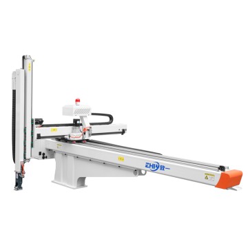
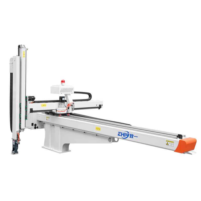
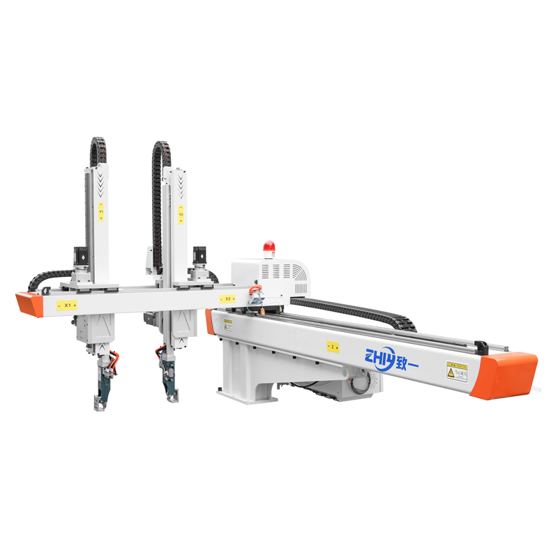
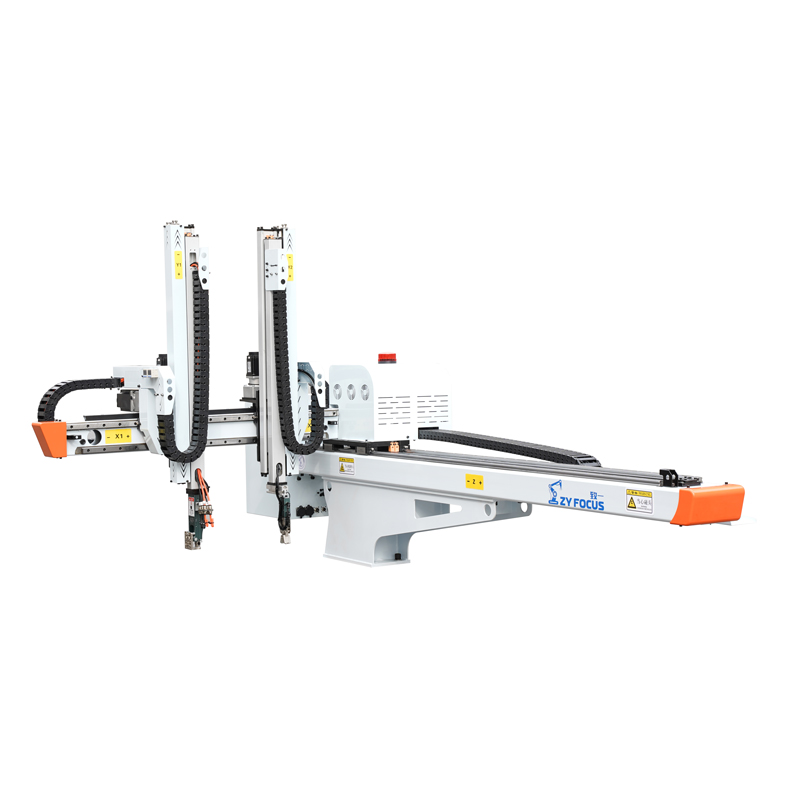
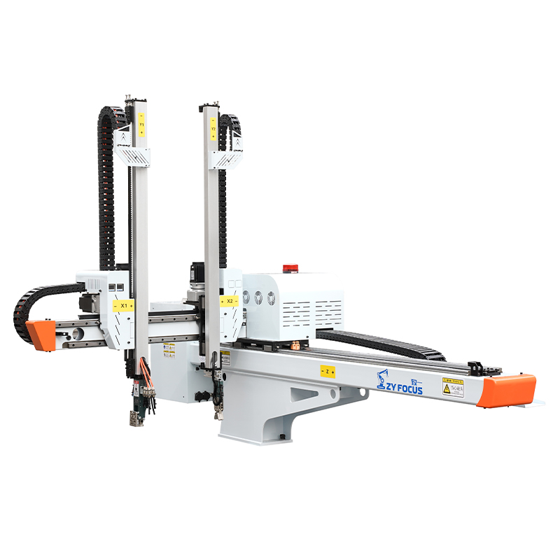
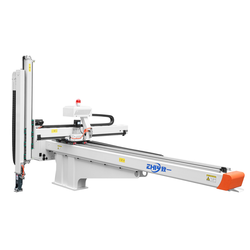
Three-axis bull head servo robot arms are widely deployed across injection molding facilities to automate part picking, insert molding, and finished product sorting. Their high 50kg maximum payload, long stroke range, and stable three-axis servo control deliver consistent output for large molds and complex plastic components. For manufacturing plant managers, procurement teams, and maintenance supervisors, stable long-term operation hinges on standardized operational protocols and scheduled preventive maintenance.
Unregulated operation and neglected upkeep trigger frequent equipment collisions, positioning drift, servo motor burnout, unplanned downtime, and inflated spare part replacement costs. This guide consolidates field-verified operational rules, tiered maintenance schedules, risk avoidance tips, and basic fault diagnosis—tailored for factory buyers and maintenance teams to maximize Robot Service life, cut operational overhead, and sustain continuous production efficiency.
Part 1: Core Operational Standards & Critical Pre-Operation Checks
All operational procedures align with ISO 10218 industrial robot safety standards, designed to eliminate collision risks and servo overload damage before production starts.
1.1 Pre-Shift Daily Inspection Checklist (Mandatory Before Power-Up)
Complete the following visual and functional checks at the start of every production shift:
- Mechanical Structure Inspection
- Scan linear guide rails, bull head vertical arm, and cross beam for plastic residue, dust, oil buildup, or metal shavings. Use dry compressed air to clear debris blocking slider movement.
- Verify all base bolts, gripper mounting screws, bull head joint fasteners, and drag chain fixing hardware remain tight; retighten loose fittings immediately to avoid vibration-induced positioning errors.
- Check drag chains for cracked cables, kinked air hoses, or binding during full-axis travel—damaged wiring causes emergency stop alarms mid-cycle.
- Pneumatic & Vacuum System Verification
- Confirm workshop air pressure stabilizes between 0.5–0.7MPa; drain accumulated water from air filter separators to prevent moisture corrosion of solenoid valves.
- Inspect suction cups, vacuum generators, and gripper cylinders for air leaks; apply soapy water to hose joints to identify hidden leaks that cause dropped products.
- Electrical & Safety Component Test
- Wipe dust from limit sensors, origin photoelectric switches, and collision detection sensors; ensure no mold runners block signal transmission.
- Test emergency stop buttons installed on the Robot Controller, bull head operation panel, and injection molding machine. Confirm all emergency stops cut servo power instantly when activated.
- Check servo cabinet cooling fans and ventilation vents; blocked airflow leads to drive overheating and automatic shutdown.
- No-Load Manual Axis Test Run After powering on and completing homing, jog each of the three axes (cross travel, vertical bull head stroke, eject stroke) at low speed through full travel limits. Watch and listen for:
- Abnormal grinding, scraping, or rattling noises from sliders, bearings, or gearboxes
- Unstable jitter or sudden speed drops during axis movement
- Out-of-limit alarm triggers indicating misaligned hard stops or soft limit parameter errors
1.2 Standard Operating Rules During Continuous Production
- Strict Load & Speed Restrictions Never operate the bull head robot above its rated maximum payload. Overloading creates permanent gearbox backlash, warps vertical bull head guide rails, and drastically shortens servo motor lifespan. When handling heavy large molded parts, reduce axis travel speed by 20–30% to balance stability and cycle efficiency.
- Mold Change & Program Modification Protocols Only certified maintenance technicians may adjust travel limits, clamping force, acceleration parameters, or production programs. After mold replacement, re-teach origin coordinates and run 10 empty test cycles before full automatic production to avoid mold collision. Save updated program files to external storage after every parameter adjustment.
- Interlock Safety Compliance Keep the robot’s mechanical interlock signal connected to the injection molding machine lockout circuit. The machine must not execute clamping cycles if the bull head arm remains inside the mold area—disabling this interlock creates catastrophic collision hazards.
- Shift-End Shutdown Procedure
- Retract the bull head vertical arm to the safe standby origin position before cutting automatic mode.
- Shut off air supply if production pauses longer than 30 minutes to reduce compressor wear and air system aging.
- Wipe down the entire robot surface, remove all plastic flash and residue from grippers and suction cups, and record any abnormal alarms or vibration observed during the shift in the equipment logbook.
1.3 Forbidden High-Risk Operations to Avoid Permanent Damage
- Do not reset fault alarms without identifying the root cause; repeated forced resets mask worsening mechanical wear or electrical failure.
- Do not modify safety soft limits or remove physical hard stop blocks to extend travel range.
- Do not operate the robot with damaged drag chains, frayed servo cables, or leaking gearboxes.
- Do not allow untrained operators to perform jogging, programming, or component disassembly near moving axes.
- Do not spray water or industrial cleaning solvents directly onto servo motors, controller cabinets, or sensor modules.
Part 2: Tiered Preventive Maintenance Schedule (Daily / Weekly / Monthly / Annual)
Scheduled maintenance is the most cost-effective way to extend bull head robot service life and cut unplanned downtime. The below schedule matches heavy-duty 24-hour injection molding workshop operating conditions.
2.1 Daily Maintenance (End of Every Shift)
- Full surface cleaning of cross beam, bull head vertical arm, guide rails, and gripper tooling.
- Air filter water drainage and vacuum cup wear inspection; replace cracked or deformed suction cups.
- Record all fault alarm codes, abnormal noise, or positioning deviation in maintenance logs.
- Quick visual check of all external wiring and air hoses for abrasion or leakage.
2.2 Weekly Maintenance (Every 7 Operating Days)
- Lubricate all linear guide rails and ball screw sliders with manufacturer-specified NLGI 2 lithium grease; apply a thin uniform coating—excess grease attracts plastic dust and creates sticky slider binding.
- Retorque all structural bolts for the bull head frame, cross beam base, and injection machine mounting brackets.
- Deep clean servo cabinet ventilation fans, filter screens, and heat sinks to prevent overheating.
- Inspect synchronous belts for cracking, slack tension, or tooth wear; adjust tension if sagging occurs during high-speed movement.
2.3 Monthly Maintenance (30 Operating Days)
- Complete calibration of origin sensors and collision detection positioning accuracy; repeat positioning tolerance must stay within ±0.03mm for precision part picking.
- Full backup of robot operating programs, servo parameters, and mold-specific subroutines to USB storage. Retain two separate backup copies off-site.
- Disassemble and clean pneumatic solenoid valves, replace aging air filter cartridges, and top up oil misters with designated pneumatic lubricant.
- Measure servo motor operating temperature during full-load cycle runs; shut down for inspection if surface temperature exceeds 60°C.
- Inspect gearbox oil levels for the bull head vertical axis; replenish or replace gear oil per operating hour milestones.
2.4 Quarterly & Annual Overhaul Maintenance
Quarterly Tasks
- Disassemble drag chains to remove accumulated dust and plastic debris, inspect internal cable insulation for micro-cracks from repeated bending.
- Test brake holding performance for all three servo axes: lock the axis at a mid-travel position, cut power, and confirm no measurable position drift.
- Adjust mechanical backlash for ball screws and gear assemblies to eliminate jitter during acceleration/deceleration.
Annual Full Overhaul (Recommended After 2,000 Operating Hours)
- Complete gearbox oil replacement for all three servo drive axes; use ISO VG460 extreme pressure gear oil specified for bull head robot gearboxes.
- Replace heavily worn consumable parts: guide rail slider wear pads, drag chain cable protection sleeves, gripper cylinder sealing rings, and aging vacuum cups.
- Full system precision recalibration across all three axes, with printed calibration test records stored for equipment audit.
- Servo drive firmware version review; apply manufacturer-released stability updates only after offline backup and test runs.
- Full electrical circuit inspection: tighten all terminal block connections, test ground wire continuity, and replace oxidized wiring connectors.
Part 3: Key Component Targeted Maintenance Guidance
3.1 Bull Head Vertical Arm Assembly (Most Wear-Prone Component)
The dual-column bull head structure bears the full load of molded products during ejection and retraction, making regular lubrication and structural checks non-negotiable:
- Clean vertical guide rails weekly to remove plastic dust, which causes dry friction and permanent rail scoring.
- Check dual-column parallelism monthly; uneven rail wear leads to arm tilting and inconsistent part picking positions.
- Inspect vertical axis gearboxes for oil seepage at shaft seals—leaks indicate failed gaskets requiring immediate replacement to avoid gear tooth abrasion.
3.2 Servo Control & Electrical System
Electrical faults account for roughly 40% of unplanned robot downtime in molding facilities. Preventative steps include:
- Maintain consistent workshop ambient temperature around the control cabinet; extreme heat accelerates drive capacitor aging.
- Avoid voltage surges by pairing robot power supplies with industrial stabilizers, especially in older factory power grids.
- Replace internal controller backup batteries every 12 months to prevent program and coordinate data loss during power outages.
3.3 End-of-Arm Tooling (Grippers & Vacuum Systems)
Tooling directly contacts molded products and suffers continuous impact wear:
- For vacuum picking applications: Check vacuum pressure sensors daily; pressure drops signal cup damage or blocked vacuum lines.
- For mechanical gripper picking: Adjust clamping force according to product weight—excessive force cracks thin plastic parts, while insufficient force causes dropped workpieces.
- Remove residual plastic flash from gripper jaws after every shift to prevent dimensional offset during clamping.
Part 4: Common Operational Faults & Rapid Troubleshooting
For procurement and maintenance teams, quick fault resolution minimizes production loss. Below are the most frequent issues observed on three-axis bull head robots and verified fixes:
- Robot fails to complete homing cycle Root Causes: Origin sensor covered in plastic residue, limit block shifted loose, damaged sensor wiring. Resolution: Clean sensor lenses, reposition and lock limit blocks, rewire broken signal cables then re-run homing calibration.
- Molded products drop during transfer cycles Root Causes: Low air/vacuum pressure, cracked suction cups, loose gripper mounting, misaligned pick coordinates. Resolution: Adjust air pressure to rated range, replace worn suction cups, retighten tooling bolts, re-teach pick origin positions.
- Axis collision alarm triggered automatically Root Causes: Program coordinate error, mold position shift, delayed injection machine interlock signal, speed set too high. Resolution: Cut power, jog robot back to safe standby, re-teach mold entry coordinates, verify interlock wiring, lower axis acceleration values.
- Abnormal grinding noise from bull head vertical axis Root Causes: Insufficient guide rail lubrication, metal debris trapped in sliders, gearbox oil depletion. Resolution: Fully clean rail and sliders, apply fresh lubricant, inspect gearbox oil level and replenish as needed.
- Servo overheating alarm during continuous production Root Causes: Blocked cabinet cooling vents, long-term overloading, aging servo fans, high ambient workshop temperature. Resolution: Clear fan filter dust, reduce payload or running speed, replace faulty cooling fans, add auxiliary ventilation near the control cabinet.
Part 5: Long-Term Asset Optimization Tips for Buyers & Plant Managers
- Document All Maintenance Records Create a standardized logbook to track lubrication cycles, component replacements, calibration dates, and fault events. Historical maintenance data helps predict wear timelines for consumable parts and optimize spare part inventory budgets.
- Match Robot Load Capacity to Production Demand Avoid running a bull head robot at its maximum rated payload 24/7. Reserve a 15–20% load safety margin to reduce mechanical fatigue and extend gearbox and servo service life. When sourcing new robots, communicate maximum product weight and mold dimensions to suppliers to select the correct payload model.
- Customize Protective Accessories for Harsh Molding Environments For workshops with heavy plastic dust, high-temperature mold zones, or frequent chemical vapor exposure, add optional full guide rail dust covers, bull head heat insulation shields, and sealed drag chain cable sleeves to cut cleaning frequency and reduce component wear.
- Train Dedicated Robot Maintenance Staff Invest in standardized operation and maintenance training for on-site technicians. Trained personnel reduce collision accidents by over 60% and catch early-stage mechanical wear before it escalates into costly full-component replacement.
- Maintain Core Spare Part Inventory Stock high-frequency consumables onsite: lubricant grease, suction cups, air filter cartridges, drag chain cable sleeves, and sensor replacement modules. Fast access to spare parts cuts downtime during unexpected breakdowns.
Conclusion
Three-axis bull head servo robot arms deliver reliable automation gains only when paired with disciplined operation and structured preventive maintenance. The combination of daily pre-shift safety checks, tiered scheduled upkeep, load control, and rapid fault resolution eliminates the majority of avoidable downtime and extends the robot’s usable service life by multiple years.
For procurement teams evaluating bull head robot solutions, prioritize suppliers that provide complete maintenance manuals, standardized lubrication specifications, and global after-sales technical support—these resources streamline long-term equipment management and reduce overall total cost of ownership for your injection molding automation line.