
Leave Your Message
Robot Cell Layout and Plant Floor Planning for Injection Molding Servo Robots
Robot Cell Layout and Plant Floor Planning for Injection Molding Servo Robots
For most plastics processors, the robot is purchased long after the floor plan is locked. That sequence is backwards. A servo robot for injection molding is not a bench-top accessory; it is a fixed piece of capital equipment that dictates machine pitch, aisle width, ceiling height, utility routing, and the entire take-out and packing flow of the cell. Getting the layout right before the machine order is placed is the difference between a cell that runs at nameplate cycle and one that is permanently choked by a 400 mm too-narrow service aisle or a guard fence that violates a safety distance. This guide walks plant owners, automation engineers, and project buyers through the concrete numbers that matter when planning a servo robot cell on a production floor.
Why Cell Layout Decisions Drive Throughput Before You Buy the Robot
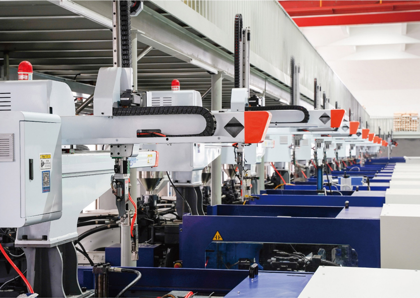
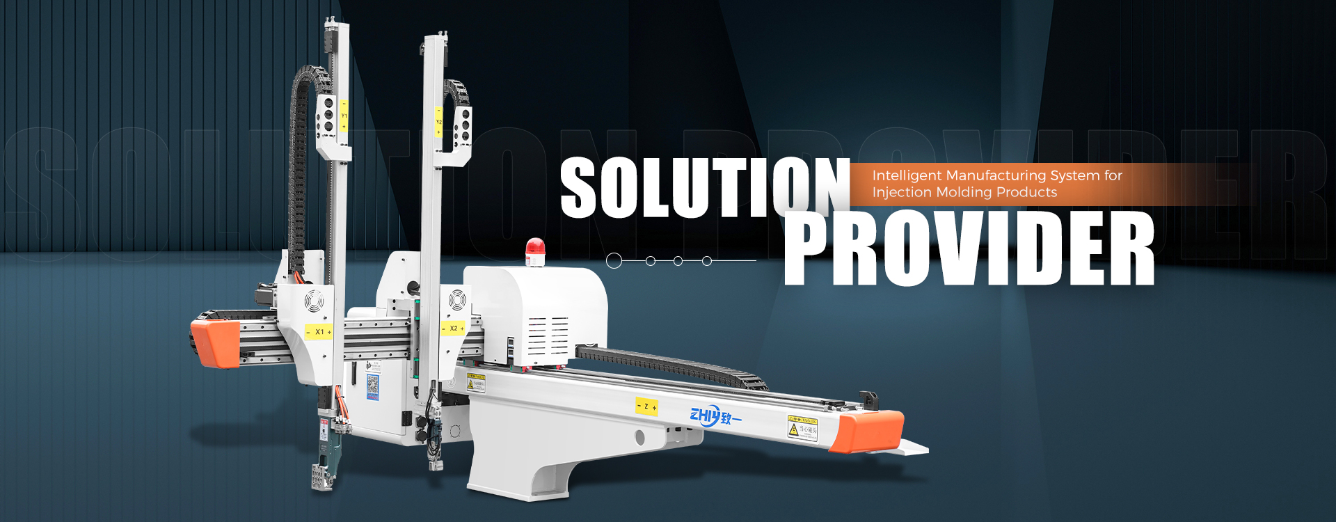
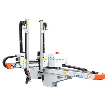
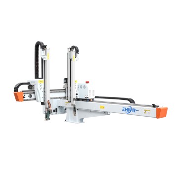
The temptation in a greenfield or retrofit project is to size the robot to the machine. In practice the constraint runs the other way: the floor and the machine pitch govern what robot geometry you can install, how fast it can cycle, and whether an operator can safely intervene. A 3-axis top-entry robot needs vertical clearance and a stable mast base; a 5-axistraverse or dual-arm unit needs lateral swing room and a longer operator-side footprint. If the cell is planned around the molding machine alone, the Robot Becomes a compromise bolted onto a space that was never designed for it.
At the planning stage, treat the robot cell as a single integrated work envelope covering the press, the end-of-arm tooling swing arc, the take-out drop point, the conveyor or buffer, and the maintenance access lane. Typical mid-size servo robot cells for 80 t to 650 t presses occupy a rectangular envelope of 3.5 m to 5.5 m in depth (machine back to conveyor front) and a width equal to the platen width plus 1.0 m to 1.8 m of operator-side working space.
Floor Footprint of a Single Robot Cell
Footprint planning starts with the robot type. The numbers below are industry-typical envelopes for top-entry servo robots and should be confirmed against the specific model's installation drawing, but they give a defensible starting point for floor allocation in a layout drawing.
3-Axis Top-Entry Cells
- Operator-side clearance for the vertical mast and traverse carriage: 0.9 m to 1.4 m.
- Take-out drop and part buffer zone in front of the guard: 0.6 m to 1.0 m.
- Total cell depth behind the machine rear: 0.8 m to 1.2 m for hydraulic, electrical, and pneumatic service.
- Resulting single-cell floor area: roughly 9 m² to 16 m² depending on press tonnage.
5-Axis and Dual-Arm Cells
- Added lateral swing envelope for the wrist and rotary axis: 0.3 m to 0.7 m per side.
- Dual-arm units double the part-handling width at the drop station, pushing operator-side clearance to 1.3 m to 1.8 m.
- Total cell floor area: roughly 14 m² to 24 m² for mid-to-large presses.
When you lay out multiple cells in a row, do not simply tile these rectangles edge to edge. The shared service corridor between two presses must absorb cabling, air lines, and a walkable maintenance path, or you will lose one of the two cells to permanent inaccessibility.
Safety Distances and Guarding: Applying ISO 13857
Safety distance is where most layouts fail compliance review. The governing standard for safeguarding is ISO 13857, which defines the minimum distance from a hazard to a guarding opening so that a person cannot reach the danger zone before the hazard is stopped. For injection molding robot cells, the relevant hazard is the moving Robot Arm and the clamp area during automatic mode.
The simplified distance formula used in layout work is:
S = K × (Tr + Ts) + C
Where K is the approach speed constant (2000 mm/s for upper-limb reach), Tr is the robot stopping time after the safety signal, Ts is the sensing and control response delay, and C is a penetration-depth compensation tied to the guard aperture. For a perimeter fence with a 12 mm to 20 mm mesh aperture and a robot stopping time around 0.3 s to 0.5 s, the resulting safety distance S typically lands in the range of 550 mm to 1200 mm from the fence inner face to the nearest moving part at full extension.
- Small apertures (e ≤ 6 mm): reach-through is blocked, so a 90 mm minimum standoff is accepted.
- Mesh 12 mm to 20 mm: maintain 550 mm to 850 mm of clear safety distance.
- Larger access openings or gates: extend to 900 mm to 1200 mm and add an interlocked gate.
- Light-curtain or laser-scanner fields: position the detection plane at the calculated S so the stopping distance is always satisfied.
Buyers should request the robot manufacturer's documented stopping-time test result, because the ISO 13857 calculation is only as good as the Tr value you plug in. A cell drawn with a guessed 0.2 s stop when the real unit needs 0.45 s is non-compliant on day one.
Machine Pitch, Aisle Width, and Ceiling Clearance
Machine pitch is the center-to-center distance between adjacent presses. It must accommodate the widest cell footprint plus the operator and service aisles on both sides. For a 250 t press with a 3-axis robot, a realistic pitch is 4.0 m to 4.8 m; for a 650 t press with a 5-axis dual-arm unit, budget 5.5 m to 6.5 m.
Aisle Width Rules of Thumb
- Operator working aisle (front of cell): 1.2 m to 1.5 m minimum for one person plus a wheeled bin.
- Maintenance and service aisle (rear): 0.9 m to 1.2 m, widen to 1.5 m if mold changes use a trolley.
- Forklift or AGV through-aisle: 2.2 m to 2.6 m clear, measured bumper to bumper of equipment.
- Emergency egress corridor: never below 1.1 m and kept free of stored totes at all times.
Ceiling and Overhead Clearance
The robot adds height to an already tall machine. A top-entry 3-axis mast can lift the vertical axis 2.5 m to 3.2 m above floor; a 5-axis unit with overhead traverse reaches 3.0 m to 3.8 m. Add a minimum 300 mm to 500 mm of clearance below any overhead service or crane beam, and verify the building's finished ceiling net height is at least 4.2 m to 5.0 m for cells that also use an overhead mold-change crane. Undersized headroom forces low-mounted ducting and lighting that later collide with the vertical stroke.
Pneumatic and Electrical Utilities: Pressure, Flow, and Cable Routing
Most servo robots run on mains power for the servo drives but still require plant air for the gripper, part ejection assist, and vacuum generators. Sizing the utility connection at layout time avoids starved grippers and pressure droop across a row of cells.
Air Supply Specification
- Operating pressure band: 0.5 MPa to 0.7 MPa (approximately 5 to 7 bar) at the robot's quick-connect.
- Per-cycle air consumption: typically 8 NL to 40 NL per pick, scaling with ejector/vacuum count and part size.
- Suggested line sizing: 10 mm to 15 mm ID supply per cell, feeding from a 20 mm to 25 mm ID ring main.
- Add a point-of-use filter-regulator-lubricator or coalescing filter to protect valves from moisture and particulate.
A row of six cells each consuming 25 NL per 12-second cycle draws a mean flow near 750 NL/min; size the compressor capacity and the ring main accordingly rather than assuming the existing shop line will absorb the load. Route pneumatic lines in a dedicated tray above the service aisle, never bundled with power cables where vibration and condensation can cause failures.
Electrical and Signal Routing
- Robot control cabinet: allocate 0.6 m × 0.6 m floor pad beside or behind the press, with 0.5 m front access.
- Power: 3-phase 380 V to 480 V depending on region; confirm the servo drive's input range before the panel is built.
- Signal handshake to the molding machine uses Euromap 67, Euromap 17, or OPC UA; leave a 1.5 m to 2.0 m service loop at the tie-in point.
- Run encoder and communication cables in a separate grounded conduit at least 200 mm from VFD power runs to avoid EMI-induced faults.
Foundation, Floor Load, and Leveling Tolerances
A servo robot mast transmits dynamic load into the floor through its base every cycle. The molding machine already imposes a static load of 8 t to 40 t depending on tonnage, and the robot cell adds point loads at the base feet. Floor planning must include the structural note, not just the painted footprint.
- Concrete slab: minimum 150 mm thick for presses up to 350 t, 200 mm to 250 mm for larger tonnage, reinforced with mesh or rebar.
- Compressive floor capacity: typically 5 t/m² to 10 t/m² for a production bay; verify with the building structural drawing.
- Leveling tolerance for the robot base: within 2 mm per 1000 mm; beyond that, the vertical axis drift degrades repeatability.
- Use machined steel shims under the base feet rather than soft packers, and re-torque after the first 200 running hours.
Drainage and pit planning also belongs on the floor drawing. If the cell includes a water-stranded conveyor or a granulator below the take-out, leave a 300 mm to 400 mm service pit with a capped floor drain so future maintenance does not require cutting the slab.
Take-Out Conveyors and Finished-Goods Flow
The robot does not add value until the part leaves the cell. The take-out conveyor direction sets the entire downstream material flow, and it should be decided on the layout, not discovered during commissioning.
- Standard drop: front-of-press belt conveyor, 0.4 m to 0.6 m wide, sloped or flat, running perpendicular to the machine axis toward the operator aisle.
- Belt speed: 8 m/min to 20 m/min, matched to the cycle so parts do not bunch or overlap at the inspection station.
- Buffering: a 1.2 m to 2.0 m accumulation length absorbs cycle jitter before packing; add a reject chute for vision-failed parts.
- Finished-goods staging: place tote or cart positions within 1.5 m of the conveyor end so the operator does not walk the floor to pack.
Design the part flow to move away from the hazard zone at all times. A common failure is a conveyor that returns the operator toward the clamp to retrieve totes, which both wastes motion and places them inside the safety perimeter during auto mode.
Multi-Machine Line Layout and Material Handling
When several cells feed a common packing or assembly line, the layout becomes a system problem. The objective is a single-directional flow with no cross-traffic between personnel and forklifts.
- Arrange cells in a U-shape or straight row so the take-out conveyors all discharge to one central pack line.
- Keep the forklift aisle on the opposite side of the building from the operator aisle to eliminate pedestrian-vehicle conflict.
- Space the pack line at least 1.8 m from the last conveyor to allow pallet building and stretch-wrapping.
- For AGV delivery of empty totes, reserve a 1.0 m wide dead-reckoning lane with floor markings and no overhead obstructions below 2.4 m.
In a multi-machine line, standardize the cell geometry so any robot can be serviced from the same side and any operator can cover three to four cells from one standing position. This reduces both training load and the floor area lost to non-standard nooks.
A Practical Pre-Project Layout Checklist
Before releasing the floor plan for construction, walk the following items with the robot supplier's installation drawing in hand:
- Confirm cell envelope from the manufacturer's footprint, not a catalog average.
- Verify ISO 13857 safety distance using the documented robot stopping time, and mark it on the floor.
- Check ceiling net height against the robot's maximum vertical reach plus 500 mm.
- Size the air ring main for total NL/min across the row, not a single cell.
- Confirm floor load, slab thickness, and leveling tolerance with the structural drawing.
- Route pneumatic, power, and signal lines in separate trays with specified separation.
- Locate take-out conveyors to discharge away from the hazard and toward packing.
- Reserve forklift and AGV aisles on a separate path from operator walkways.
Tip: Always add a 10% to 15% contingency to every aisle and pitch dimension on the drawing, because real guarding, cable trays, and bin storage always consume more floor than the CAD model suggests.
Frequently Asked Questions
What is the minimum safety distance for a servo robot guard fence?
Using ISO 13857 with a 2000 mm/s approach constant and a typical 0.3 s to 0.5 s robot stopping time, a perimeter fence with a 12 mm to 20 mm aperture needs roughly 550 mm to 850 mm of clear distance from the fence to the nearest moving part. Larger gates or slower stops push this to 900 mm to 1200 mm, and the value must be recalculated from the manufacturer's tested stopping time rather than an estimate.
How much ceiling height do I need for a 5-axis robot cell?
A 5-axis top-entry or traverse unit typically reaches 3.0 m to 3.8 m above the floor at full vertical extension. Add 300 mm to 500 mm of service clearance and, if an overhead mold crane is used, plan for a finished net ceiling height of 4.2 m to 5.0 m. Measure the building height before ordering, because low ducting or lighting often collides with the vertical stroke.
What air pressure and consumption should the plant supply?
Size the cell for 0.5 MPa to 0.7 MPa at the robot quick-connect, with per-cycle consumption of about 8 NL to 40 NL per pick depending on gripper and vacuum count. For a row of cells, sum the mean flow across all robots and size the ring main and compressor to that total rather than to a single machine, and fit a point-of-use filter-regulator to protect the valves.
How level must the robot base be?
Keep the robot base within 2 mm per 1000 mm of level. Beyond this tolerance the vertical axis drifts and repeatability suffers, which shows up as inconsistent part placement and occasional missed picks. Use machined steel shims under the feet and re-check the level after the first 200 running hours as the foundation settles under dynamic load.
How wide should aisles be between molding machines?
Plan a 1.2 m to 1.5 m operator aisle in front of the cell, a 0.9 m to 1.2 m service aisle behind it, and a 2.2 m to 2.6 m forklift or AGV through-aisle. Emergency egress corridors must stay at or above 1.1 m and remain clear of stored totes. Machine pitch then becomes cell width plus these aisles, typically 4.0 m to 6.5 m center-to-center.
Can I place the take-out conveyor on either side of the press?
You can, but the layout should discharge parts away from the clamp hazard and toward the packing or inspection station. A conveyor that forces the operator back toward the moving arm during auto mode creates both a safety and an efficiency problem. Standard practice is a front-of-press belt running perpendicular to the machine axis toward the operator aisle with a short accumulation buffer.