
Leave Your Message
0102030405
How to Choose Robot Based on Speed
2026-06-30
How to Choose Robot Based on Speed: A Complete Buyer’s Guide to Match Cycle Time & Throughput
Table of Contents
- Introduction: Why Speed Is the Core Metric for Robot Procurement
- Key Speed Metrics Every Buyer Must Understand 2.1 TCP Linear Speed vs Joint Rotational Speed 2.2 Cycle Time: The Real-World Benchmark, Not Peak Speed 2.3 Acceleration & Deceleration: Hidden Drivers of Actual Throughput
- Critical Factors That Reduce A Robot’s Practical Operating Speed 3.1 Total Payload & Center of Gravity Offset 3.2 Working Reach & Motion Stroke Distance 3.3 Precision Requirements & Process Stability 3.4 Mechanical Rigidity & Robot Type Architecture
- Robot Type Speed Comparison: Match Machine to Your Takt Time Target 4.1 Delta Parallel Robots: Ultra-High Speed for Light Pick-and-Place 4.2 SCARA Robots: Balanced Speed for Flat Assembly & PCB Handling 4.3 6-Axis Articulated Robots: Versatile Mid-Range Speed for Complex Motion 4.4 Collaborative Robots: Low-Speed Human-Shared Workspace Operation 4.5 Gantry / Cartesian Robots: Steady Linear Speed for Large Work Zones
- Step-by-Step Workflow to Select Robots By Speed Requirements Step 1: Calculate Your Target Takt & Required Cycle Time Step 2: Compute Full Effective Payload (Workpiece + End Effector) Step 3: Measure Full Motion Stroke & Maximum Reach Step 4: Balance Speed Against Precision & Process Limits Step 5: Validate Robot Performance With Manufacturer Cycle Data Step 6: Reserve Speed Safety Margin for Long-Term Production
- Common Speed-Related Robot Selection Mistakes Buyers Make
- Real-World Application Speed Matching Examples
- Final Checklist for Speed-Driven Robot Sourcing
- FAQ: Robot Speed Selection for Global Manufacturing Buyers
Introduction: Why Speed Is the Core Metric for Robot Procurement
For manufacturing procurement teams, robot speed directly dictates production line throughput, unit cost per product, and overall return on automation investment. Many buyers only reference advertised peak speed values from robot datasheets, yet find the deployed robot fails to hit required line rates after installation.
The disconnect stems from misunderstanding how speed interacts with payload, reach, precision, and mechanical design. A robot’s maximum theoretical speed rarely translates to real production cycle performance. This guide breaks down how to evaluate robot speed from a procurement perspective, compare different robot architectures, and create a repeatable selection process aligned with your factory’s takt time goals.
This guide targets global automation buyers, production engineers, and factory procurement managers evaluating robotic equipment for packaging, assembly, material handling, machining, and sorting applications.
Key Speed Metrics Every Buyer Must Understand
Before comparing robot models, clarify three non-negotiable speed metrics used across international robot manufacturers and ISO 9283 testing standards.
2.1 TCP Linear Speed vs Joint Rotational Speed
Tool Center Point (TCP) linear speed measures how fast the robot’s end effector moves in straight Cartesian lines, recorded in mm/s or m/s. This is the most relevant metric for pick-and-place, packaging, and assembly tasks.
Joint rotational speed describes how quickly individual robot axes rotate, measured in °/s. This metric matters for complex angled movements like welding, trimming, or multi-orientation part manipulation.
Manufacturers often highlight high joint speeds in marketing materials, but TCP linear speed is the benchmark for throughput-focused applications. Always prioritize TCP speed comparisons when sourcing robots for repetitive handling tasks.
2.2 Cycle Time: The Real-World Benchmark, Not Peak Speed
Peak TCP speed is achieved only during short, unobstructed movement segments. Cycle time measures the full duration of a complete work sequence: pick, travel, orient, place, and return to home position. It is the single most reliable indicator of a robot’s actual production capacity.
Industry standard ISO 9283 defines standardized pick-and-place cycle tests (1kg payload, 305mm horizontal travel, 25mm vertical lift) to enable cross-brand robot comparisons. Always ask suppliers for ISO-standard cycle time data instead of relying on isolated peak speed figures.
2.3 Acceleration & Deceleration: Hidden Drivers of Actual Throughput
A robot’s ability to rapidly accelerate and decelerate impacts cycle time more than maximum sustained speed. High acceleration cuts travel time between work points, especially for short-stroke high-frequency tasks like food sorting or electronic component assembly.
Delta robots deliver acceleration exceeding 100 m/s², while heavy-payload 6-axis palletizing robots top out at 10–15 m/s². Slower acceleration increases cycle time drastically for lines requiring over 60 cycles per minute. When sourcing, request acceleration curve charts for your target payload range.
Critical Factors That Reduce a Robot’s Practical Operating Speed
No robot runs at its datasheet peak speed during full production. Four core variables permanently lower real-world operating velocity, and buyers must account for these during technical evaluation.
3.1 Total Payload & Center of Gravity Offset
Datasheet speed ratings are tested under near-lightweight conditions. As total payload rises (workpiece + gripper + camera or cutting tools), manufacturers automatically limit acceleration and maximum TCP speed to reduce mechanical stress and vibration.
A 1kg rated SCARA robot can lose 10–18% of its cycle speed when carrying a 1.5kg total load. Parts with off-center mass (unbalanced payloads) create additional rotational inertia, further slowing motion and reducing positioning stability.
Procurement best practice: Calculate full effective payload including all end-of-arm tooling, not just the workpiece itself.
3.2 Working Reach & Motion Stroke Distance
Robot speed performance degrades when operating near maximum arm reach. Extended arm length amplifies inertia during rapid direction changes, forcing motion controllers to cap speed to avoid arm deflection and positioning error.
Short travel strokes (under 300mm) unlock a robot’s full acceleration potential for ultra-fast cycles. Long cross-cell travel (over 1 meter) reduces average TCP speed significantly, even if peak speed remains high on paper.
3.3 Precision Requirements & Process Stability
Speed and repeatability share an inverse tradeoff. High-speed movement generates inertial vibration, leading to positioning overshoot and inconsistent part placement.
- High-precision micro-assembly (±0.01mm repeatability): Must limit speed to reduce arm shake
- Packaging, bulk sorting, palletizing: Looser precision tolerances allow full speed operation
- Coating, laser welding, surface finishing: Constant controlled speed is required; sudden acceleration ruins process quality
Buyers must define minimum repeatability tolerances before setting acceptable robot operating speed limits.
3.4 Mechanical Rigidity & Robot Type Architecture
Lightweight parallel link delta robots feature minimal moving mass, supporting extreme speed. Heavy cast 6-axis robots built for 200kg+ payloads require thicker gearboxes and large drive motors, creating higher moving mass that caps maximum acceleration and linear velocity.
Collaborative robots add another layer of speed limitation: global safety standards ISO/TS 15066 enforces low force and velocity limits during human-robot shared operation, capping practical TCP speed under 2.5 m/s for unguarded workcells.
Robot Type Speed Comparison: Match Machine to Your Takt Time Target
Each robot mechanical design has a defined speed performance window. Below is a procurement-focused breakdown of typical throughput ranges and ideal use cases organized by speed tier.
4.1 Delta Parallel Robots: Ultra-High Speed for Light Pick-and-Place
- Typical TCP speed: 8,000–12,000 mm/s
- Standard cycle rate: 150–300 picks per minute
- Maximum recommended payload: 0.1–3kg
- Best for: Food packaging, pharmaceutical blister sorting, electronics small part picking
- Speed advantage: Stationary base-mounted actuators cut moving mass, enabling extreme acceleration for short-stroke rapid repetition
4.2 SCARA Robots: Balanced Speed for Flat Assembly & PCB Handling
- Typical TCP speed: 6,000–10,000 mm/s
- Standard cycle rate: 80–140 picks per minute
- Maximum recommended payload: 0.5–20kg
- Best for: PCB component insertion, screw fastening, small consumer goods assembly
- Speed advantage: Rigid vertical axis maintains precision while retaining fast horizontal planar movement
4.3 6-Axis Articulated Robots: Versatile Mid-Range Speed for Complex Motion
- Typical TCP speed: 1,000–5,000 mm/s
- Standard cycle rate: 10–60 cycles per minute
- Maximum recommended payload: 3–800kg
- Best for: Automotive welding, case palletizing, machine tool tending, multi-angle part handling
- Speed tradeoff: Full orientation flexibility sacrifices raw linear speed compared to delta/SCARA units
4.4 Collaborative Robots: Low-Speed Human-Shared Workspace Operation
- Typical collaborative mode TCP speed: 1,000–2,500 mm/s
- Standard cycle rate: 10–25 cycles per minute
- Maximum recommended payload: 3–30kg
- Best for: Low-volume mixed SKU assembly, hand-guided material transfer, small-batch finishing
- Speed limitation: Safety force thresholds restrict acceleration; fencing is required to unlock higher speed operation
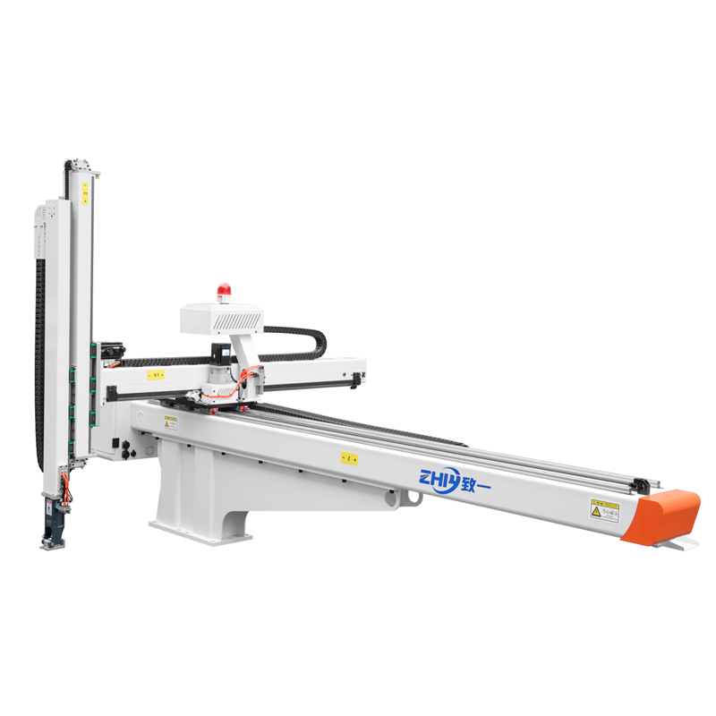
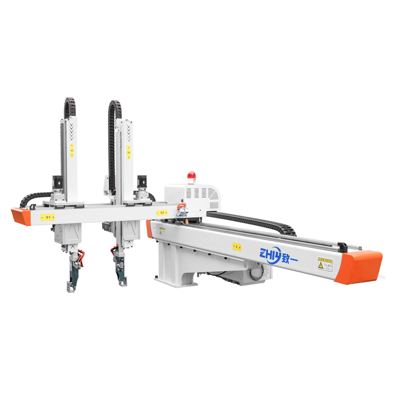
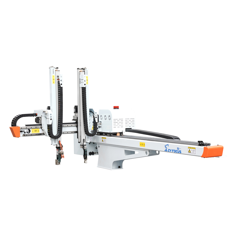
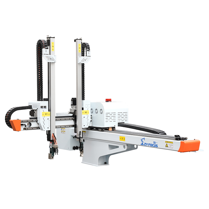
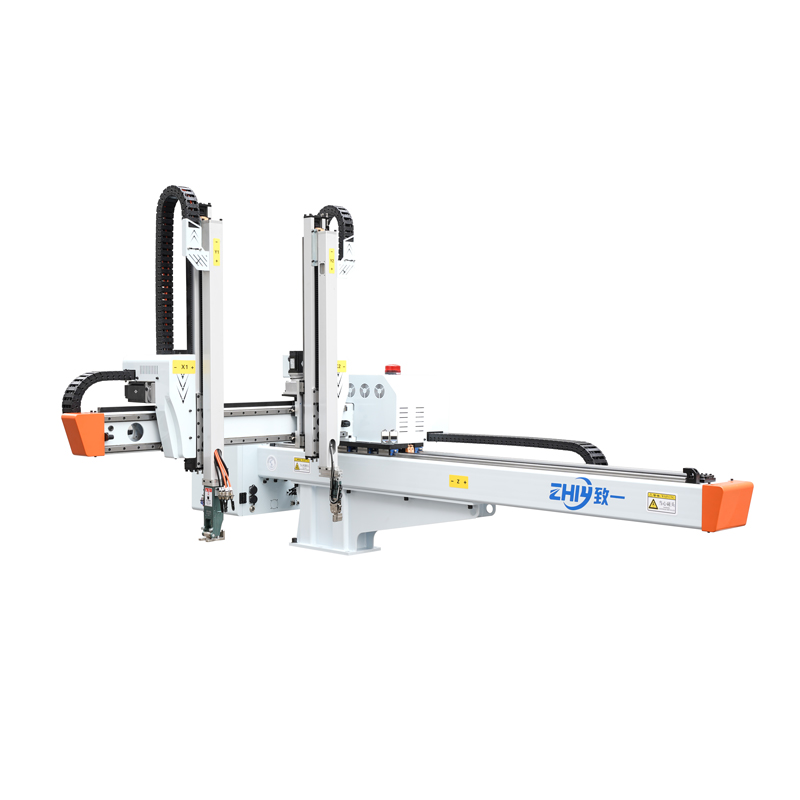
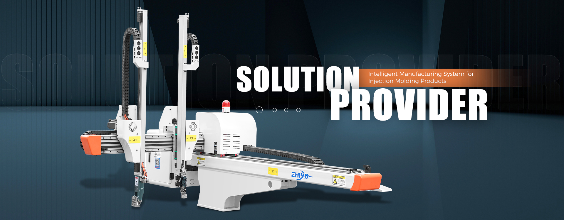
4.5 Gantry / Cartesian Robots: Steady Linear Speed for Large Work Zones
- Typical TCP speed: 2,000–6,000 mm/s
- Standard cycle rate: 5–40 cycles per minute
- Maximum recommended payload: 5–200kg
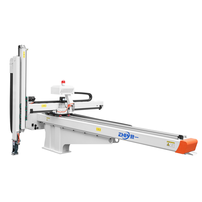
- Best for: Large panel handling, warehouse bin picking, long-span machining automation
- Speed characteristic: Consistent linear motion speed across full travel length, limited acceleration on long rails
Step-by-Step Workflow to Select Robots By Speed Requirements
Follow this standardized process to eliminate guesswork and avoid underperforming robot purchases.
Step 1: Calculate Your Target Takt & Required Cycle Time
Start with line output targets. Divide total daily production volume by available operating minutes to find required parts per minute (PPM). Convert PPM to maximum allowable single robot cycle time.
Add a 10–15% buffer for conveyor delays, part feeding inconsistencies, and maintenance downtime to avoid robot bottlenecks during peak production shifts.
Step 2: Compute Full Effective Payload (Workpiece + End Effector)
Sum the weight of the product, gripper, vision camera, cutting tool, and any cabling mounted on the robot flange. Note center-of-gravity offset distance from the TCP. Share this full payload data with suppliers to receive accurate derated speed performance data.
Step 3: Measure Full Motion Stroke & Maximum Reach
Map every movement point the robot must travel: pick station, processing station, placement station, and home position. Record horizontal travel distance, vertical lift height, and maximum arm extension during operation. Suppliers use stroke and reach data to simulate real cycle time performance.
Step 4: Balance Speed Against Precision & Process Limits
Document minimum repeatability and process speed stability rules. If your application requires tight positioning or constant feed speed for coating/welding, reduce target robot speed expectations and prioritize rigid robot models over maximum throughput options.
Step 5: Validate Robot Performance With Manufacturer Cycle Data
Request ISO standardized cycle test reports for your exact payload and stroke parameters. Reject generic peak speed datasheets that do not reflect your production conditions. Ask suppliers to provide digital motion simulation videos matching your workcell layout to verify cycle time output.
Step 6: Reserve Speed Safety Margin for Long-Term Production
Over time, robot gearboxes and bearings experience minor wear that gradually reduces acceleration and cycle speed. Procurement teams should select a robot model that delivers 15–20% faster cycle performance than your minimum takt requirement to maintain throughput over 5–8 years of continuous operation.
Common Speed-Related Robot Selection Mistakes Buyers Make
- Only comparing peak TCP speed without reviewing real cycle time data
- Ignoring gripper and tool weight when calculating effective payload
- Selecting cobots for high-throughput lines without planning safety fencing upgrades
- Choosing ultra-high-speed delta robots for heavy workpieces over 3kg
- Neglecting reach-induced speed derating for long cross-cell travel paths
- Skipping production simulation and relying solely on marketing specification sheets
- Failing to account for speed degradation from vibration-sensitive precision processes
Real-World Application Speed Matching Examples
Example 1: High-Speed Snack Packaging
Target: 220 parts per minute, 0.2kg total payload, short 280mm horizontal stroke Robot Match: Delta parallel robot, 10,000mm/s TCP speed, 0.35s standard cycle time Rationale: Light payload and short travel unlock delta’s maximum acceleration advantage to hit throughput targets.
Example 2: Automotive Component Assembly
Target: 35 cycles per minute, 12kg total payload, complex multi-angle part rotation Robot Match: Mid-range 6-axis articulated robot, 3,800mm/s TCP speed Rationale: Full 6-axis orientation flexibility outweighs raw linear speed; moderate payload does not drastically derate cycle performance.
Example 3: Small Batch Electronic Assembly With Human Operators
Target: 18 cycles per minute, 2kg payload, shared workspace Robot Match: Collaborative robot, 2,000mm/s collaborative mode TCP speed Rationale: Low throughput target aligns with safety speed limits; eliminates costly safety fencing for frequent product changeovers.
Example 4: End-of-Line Case Palletizing
Target: 12 cycles per minute, 50kg box payload, maximum 2.2m vertical reach Robot Match: Heavy-duty 6-axis palletizing robot, 2,600mm/s TCP speed Rationale: High payload inherently limits speed; large reach prioritizes structural rigidity over fast acceleration.
Final Checklist for Speed-Driven Robot Sourcing
Before finalizing robot purchase orders, confirm all below speed-related deliverables from suppliers:
- ISO 9283 standardized cycle time test data at your full effective payload
- TCP acceleration/deceleration curve charts matching your workpiece weight
- Motion simulation output with your exact workcell travel distances
- Speed derating documentation for maximum arm reach operation
- Long-term mechanical wear impact on cycle speed over 5+ years of runtime
- Safety mode speed limits (for cobot models) and fencing upgrade options for higher throughput
- Payload offset testing data for unbalanced end-of-arm tooling
FAQ: Robot Speed Selection for Global Manufacturing Buyers
Q1: Is higher TCP speed always better for production lines?
A1: No. Extreme speed introduces vibration, positioning error, and accelerated mechanical wear. If your process requires tight precision or consistent surface treatment motion, moderate controlled speed delivers better product quality and lower maintenance costs. Only prioritize maximum speed for loose-tolerance, high-volume pick-and-place tasks.
Q2: How much cycle time loss should I expect from heavier payloads?
A2: On average, every additional 0.5kg of payload increases single cycle time by 5–15%, depending on robot architecture. Delta robots see the steepest speed drop when payload exceeds 3kg, while heavy-duty 6-axis robots have milder derating curves for loads under their rated maximum.
Q3: Can I adjust robot controller settings to boost operating speed after installation?
A3: Minor speed tuning is possible within controller software limits, but hardware constraints (motor size, gearbox torque, arm rigidity) create fixed upper boundaries. Cranking speed beyond manufacturer recommended limits voids warranties and accelerates component failure.
Q4: When should I choose a SCARA instead of a delta robot for fast assembly?
A4: Select SCARA if your process requires vertical pressing, screw insertion, or workpieces heavier than 3kg. Delta robots excel at ultra-light, purely horizontal pick-and-place, while SCARA balances fast planar movement with rigid vertical precision for assembly tasks.
Q5: How do I compare speed performance across different robot brands fairly?
A5: Request standardized ISO cycle test data using identical payload, stroke, and lift height parameters. Avoid comparing peak speed values pulled from separate datasheets, as manufacturers test maximum velocity under different unloaded conditions that do not reflect real factory operation.