
Leave Your Message
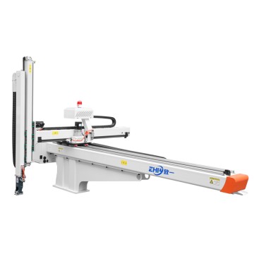
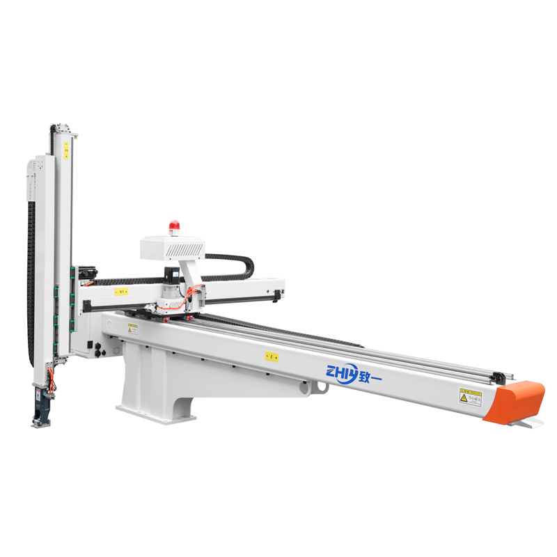
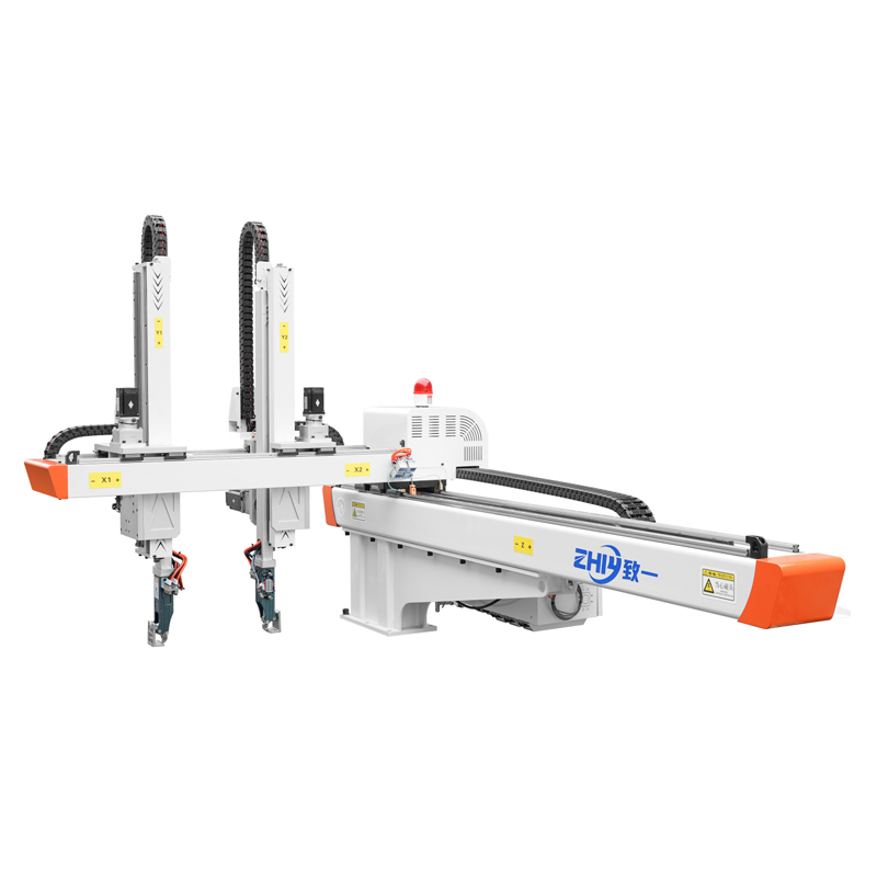
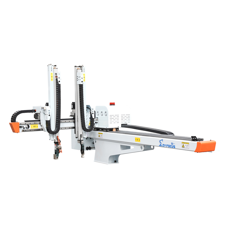
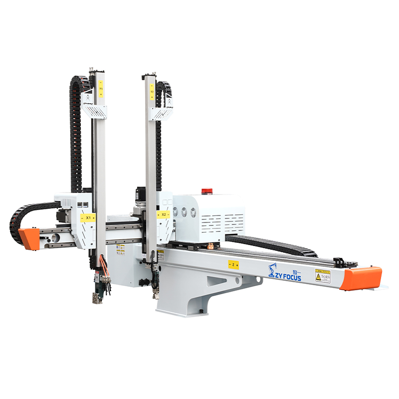
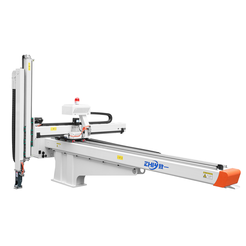
Five Axis Double Arm: End-of-Arm Tooling Compatibility
Five Axis Double‑Arm: End‑of‑Arm Tooling Compatibility
For injection‑molding automation buyers, the performance of a five‑axis double‑arm robot is only as good as the end‑of‑arm tooling (EOAT) attached to it. Many procurement teams focus heavily on robot payload, cycle time and positioning accuracy during evaluation, yet overlook EOAT compatibility. Mismatched mechanical flanges, misaligned signal communication or poorly balanced dual‑arm tooling can lead to extended setup delays, frequent part dropping, unplanned downtime and inflated integration costs.
This article breaks down core compatibility considerations, common pain points, practical evaluation criteria and real‑world application insights for five‑axis double‑arm systems. It helps plant managers, automation engineers and procurement specialists make more informed buying and integration decisions.
What Makes Five‑Axis Double‑Arm EOAT Compatibility Unique
Single‑Arm Robotic systems have relatively straightforward tool‑mounting requirements. Double‑arm five‑axis units bring a new set of challenges because two independent working arms operate within shared working envelopes.
Each arm can carry separate tooling to complete parallel tasks: one arm extracts finished plastic parts, while the other handles sprues, inserts or secondary positioning work. This dual‑function capability is one of the main reasons factories invest in five‑axis double‑arm robots. However, compatibility does not stop at fitting each tool onto each arm.
Key unique characteristics include:
- Dual‑arm load balance: The weight, inertia and center‑of‑gravity of tooling on each arm influence overall dynamic performance. Heavier or bulkier EOAT on one arm may trigger vibration, positioning drift or safety overload alarms under high‑speed cycling.
- Interference risk: Physical dimensions of grippers, suction cups and connecting hardware must avoid collision when two arms move simultaneously inside mold space and extraction paths.
- Synchronized signal handling: Pneumatic lines, sensor feedback and control signals for two separate EOAT sets need reliable coordination through the robot’s main controller. Poor signal matching causes desynchronized actions and production faults.
- Mixed‑tool flexibility: Factories frequently want to run different tool types on each arm, for example vacuum suction on one arm and mechanical gripper on the other. Compatibility must support mixed‑tool configurations without heavy custom modification.
Core Compatibility Factors To Evaluate Before Purchase
When reviewing five‑axis double‑arm robot options, assess these four core compatibility dimensions alongside your existing or planned end‑of‑arm tool library.
Mechanical Interface Standardization
Mechanical compatibility starts with mounting flange specifications. Standardized mounting interfaces greatly reduce custom‑adapter costs and cut tool‑change downtime.
Buyers should verify:
- Flange dimension specifications for both Robot Arms, confirming consistency with widely‑accepted industrial mounting standards. Different flange sizes between the two arms will restrict tool‑sharing and increase spare‑part inventory.
- Allowable mounting offset and moment load, not just static payload rating. Many integration failures come from ignoring torque and bending moment generated by offset‑mounted grippers, even when tool weight stays under the robot’s listed payload value.
- Physical clearance around the mounting flange. Some robot designs leave limited surrounding space, making installation of quick‑change modules, valves and sensor housings difficult.
Custom‑machined adapter plates are possible, but they add lead‑time, integration expense and potential alignment error. Prioritize robot platforms built around common mechanical standards if you plan to reuse existing EOAT inventory across multiple work cells.
Pneumatic and Electrical Connection Compatibility
Even with perfect mechanical fit, mismatched air routing and electrical interfaces will prevent stable operation.
Check the following points:
- Number of built‑in pneumatic channels for each arm. Dual‑tool setups often require extra air circuits for multiple grippers, suction zones and blow‑off functions. Insufficient onboard air channels force external cable harnesses that snag during fast movements.
- Electrical signal layout: I/O count, connector type and signal voltage range. If you deploy tooling with part‑presence sensors, pressure sensors or force feedback modules, confirm the Robot Controller can receive and process those signals natively. Extra external relay boxes increase complexity and failure points.
- Cable‑chain routing capacity. Bulky combined pneumatic‑electrical bundles degrade cycle performance and wear quickly in high‑frequency injection‑molding environments.
Controller and Software Integration
True compatibility extends into robot control logic. Physically attaching a gripper or suction tool does not guarantee seamless coordination of dual‑arm workflows.
Important software‑related considerations:
- Native support for independent EOAT parameter setup for each arm. You want separate grip‑force, delay‑time and sensor‑trigger configurations for arm A and arm B without complex workaround programming.
- Compatibility with tool‑change workflows. If you intend to deploy automatic tool changers for frequent product‑model switching, confirm the robot control system supports tool‑change logic, payload offset remapping and safety interlock functions.
- Diagnostic feedback. Reliable systems deliver clear alarm logs for EOAT‑related faults such as sensor signal loss, air‑pressure drop or overload conditions. Clear diagnostics shorten troubleshooting time on the production floor.
Application‑Specific Constraints For Injection‑Molding Environments
Injection workshops create demanding operating conditions for both robot and tooling. Compatibility assessments need to account for real‑factory conditions.
- Temperature and dust exposure. Heat radiating from molds, fine plastic dust and occasional oil mist place stress on connectors and tool components. Confirm that combined robot‑and‑tool assemblies maintain suitable protection ratings for your shop‑floor environment.
- Cycle‑rate impact. Large‑size or high‑inertia EOAT will lower maximum achievable cycle speed. When evaluating samples or tender specifications, test tool‑mounted dynamic performance under real‑production cycle parameters rather than only reviewing static payload figures.
- Insert‑molding special requirements. For insert‑placement processes, dual arms often carry insert fixtures and part‑extraction tooling simultaneously. In these cases, moment load, positional repeatability and anti‑interference layout become critical compatibility indicators.
Common Real‑World Compatibility Pitfalls
Based on field‑deployment feedback, these are the most frequent compatibility mistakes made during five‑axis double‑arm robot procurement and integration.
- Only checking static payload rating Buyers match tool weight to robot‑spec payload but ignore moment and offset load. The result is vibration during fast moves, reduced positioning repeatability and unexpected safety stops. Always evaluate moment‑load specifications for each arm.
- Assuming existing single‑arm EOAT works directly on double‑arm hardware Tooling that performs well on single‑arm robots may create interference risks when mounted on a double‑arm unit. The two arms share overlapping working zones; tool‑body size and protruding sensor housings can cause collision during coordinated motion.
- Underestimating wiring and pneumatic‑channel requirements Teams select robots without reserving enough onboard air and signal channels for dual‑tool configurations. Projects then require expensive post‑sale modification, extending commissioning timelines.
- Neglecting tool‑change compatibility for high‑mix production Many buyers focus on the first‑batch product only. Without standardized interfaces, every future product change will require custom‑built adapters and lengthy re‑commissioning, hurting long‑term production flexibility.
Practical Checklist For Your Procurement Evaluation
Use this practical checklist when you compare five‑axis double‑arm robot solutions against your EOAT inventory and future‑production roadmap.
- Confirm mechanical‑flange specifications for both arms, compare against your existing or planned tooling
- Review static payload plus allowable moment and offset load for each arm
- Count available pneumatic channels and I/O signals per arm for dual‑tool operation
- Verify controller support for independent EOAT parameter settings for each arm
- Check physical clearance for mounting quick‑change modules, valves and sensors
- Assess risk of mechanical interference between two sets of tooling within mold‑access travel paths
- Confirm diagnostic‑alarm coverage for tool‑related faults
- Validate that the combined robot‑and‑tool assembly fits your shop‑floor temperature and dust‑level operating environment
- Discuss integration‑support scope: whether the vendor provides simulation or testing for your target EOAT combinations
Conclusion
End‑of‑arm tooling compatibility defines the real‑world flexibility of five‑axis double‑arm robotic systems. Robot speed, payload and precision only deliver value when paired with well‑matched tool‑mounting, connection and control‑system integration.
For procurement and engineering teams, compatibility assessment should run in parallel with robot‑hardware evaluation, not treated as an after‑thought during installation. By reviewing mechanical interfaces, pneumatic‑electrical connections, controller capabilities and application‑specific constraints early in the buying cycle, you can minimize integration risk, shorten commissioning time and unlock the full dual‑arm productivity advantage for your injection‑molding operations.
Even when working with limited‑volume custom‑tool requirements, prioritizing standardized interfaces will reduce your total‑cost‑of‑ownership over the machine’s service life.
Frequently Asked Questions
Q: Can I fit different types of EOAT on each arm of a five‑axis double‑arm robot? A: Yes. Mixed‑tool configurations (vacuum suction on one arm, mechanical gripper on the other) are common for insert molding and multi‑step part‑handling workflows. You need to verify mechanical clearance, independent parameter‑setting support and signal‑channel availability on the robot side to avoid interference or programming bottlenecks.
Q: Is it necessary to invest in automatic tool changers for five‑axis double‑arm setups? A: Not for low‑mix high‑volume production. For high‑mix manufacturing with frequent product‑switching, automatic tool changers reduce manual‑swap‑out time and human error. Keep in mind that dual‑arm layouts double the hardware requirements for tool‑change systems.
Q: What is the biggest hidden cost caused by poor EOAT compatibility? A: Extended commissioning time and unplanned production downtime. Custom adapter fabrication, additional wiring modification and on‑site troubleshooting push‑back project timelines. Long‑term, non‑standard interfaces also increase spare‑part complexity and maintenance overhead.
Q: Should I test my actual EOAT before final robot purchase? A: Whenever possible. Request simulation or physical test‑run validation using representative tool‑samples. This reveals interference, moment‑load and signal‑matching issues before placing large‑scale equipment orders.