
Leave Your Message
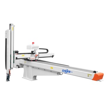
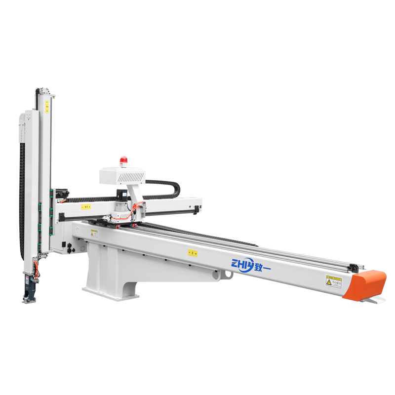
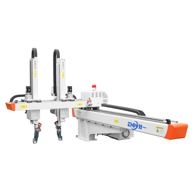
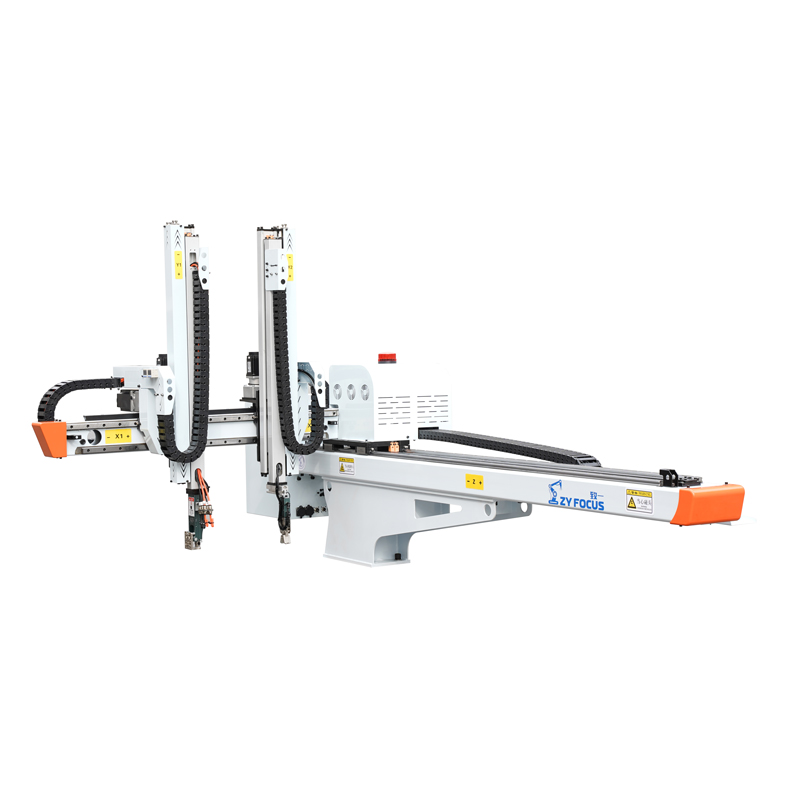
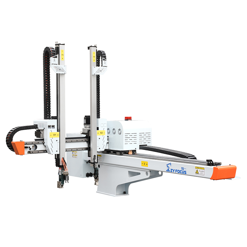
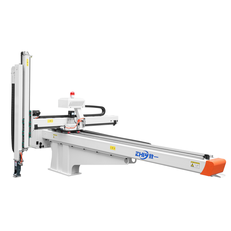
Bull Head Robot Arm: Bearing and Joint Design Analysis
Bull Head Robot Arm: Bearing and Joint Design Analysis
In injection molding automation, bull‑head three‑axis Servo Robot Arms are widely adopted for heavy‑duty part removal, complex mold handling and high‑cycle production lines. Many equipment buyers focus on payload, stroke length and cycle time when comparing specifications, yet overlook bearing and joint construction, which directly defines long‑term repeatability, downtime frequency and total‑cost‑of‑ownership. Even units with matching nominal payload can deliver vastly different real‑world performance, largely due to decisions made in joint structure and bearing selection. This article breaks down practical design considerations to help procurement and engineering teams evaluatebull‑head robot arms from a mechanical foundation perspective.
What Makes Bull‑Head Manipulator Joints Mechanically Unique
Bull‑head style robot arms carry distinct load patterns compared to general‑purpose Robotic Arms. The overhead beam layout creates significant cantilever moment whenever the arm extends outward to extract large, heavy molded products. Each joint must absorb mixed dynamic loads: radial force, axial thrust and continuous tilting moment during high‑speed acceleration and deceleration cycles.
Unlike compact collaborative robots, injection molding bull‑head robots run millions of repetitive pick‑and‑place cycles annually. Joint assemblies face frequent direction reversals, sudden stop‑and‑go movements, plus minor vibration transmitted from the injection molding machine. Poor joint design shows symptoms gradually: drifting positioning, increased mechanical noise, visible play during movement, and premature component failure that triggers unplanned production stops.
Key mechanical challenges for bull‑head robot joints:
- Sustained cantilever moment when the horizontal beam reaches maximum extension
- Repeated direction reversal creating fluctuating impact loads across all joint axes
- Balance requirement between structural rigidity and overall machine weight
- Contaminant exposure from factory dust, plastic fine particles and temperature variation
Buyers often underestimate how these cyclic forces wear joints over thousands of operating hours. Two robot arms with identical published payload ratings can diverge sharply after one‑year continuous operation, depending on joint and bearing architecture.
Bearing Selection: Core Components That Shape Joint Performance
Bearings serve as the critical interface within every rotational and linear joint of bull‑head robot arms. Material grade, bearing type, preload configuration and sealing design collectively influence rigidity, friction, service life and maintenance frequency. For heavy‑load bull‑head models rated for high payload, manufacturers commonly select among several bearing solutions for different joint positions.
Crossed Roller Bearings for Primary Rotation Joints
Major rotary joints on bull‑head manipulators frequently use crossed roller bearings. Cylindrical rollers are arranged at 90‑degree alternating angles inside a compact housing. Within a small installation space, this bearing type supports radial load, bidirectional axial load and large tilting moment simultaneously, which perfectly matches the cantilever stress from extended horizontal beams.
Well‑implemented crossed‑roller bearing joints deliver high rigidity with minimal elastic deflection under full payload. For buyers, this translates into stable repeat positioning even when the arm stretches to maximum working stroke. The downside comes from higher component and assembly cost. Cost‑optimized alternatives may substitute with standard ball‑bearing combinations, requiring multiple bearing sets stacked to handle moment loads. Stacked configurations introduce additional assembly clearances that degrade long‑term rigidity.
Angular‑Contact Ball Bearings for Secondary Joint Positions
Angular‑contact ball bearings handle combined radial‑and‑axial loads and suit medium‑stress joint locations. They are typically deployed in secondary rotating axes where tilting moment is lower than the main bull‑head joint. To eliminate backlash, these bearings are installed in pairs with controlled preload.
A common design flaw observed on low‑cost bull‑head robots is insufficient or inconsistent preload. Initial performance appears acceptable, yet preload relaxes after thousands of cycles. Joint clearance gradually appears, bringing positioning drift and louder operating noise.
Linear Guide Bearings for Horizontal and Vertical Axes
Linear joints on bull‑head robots rely on precision linear guide bearings. Since the horizontal beam bears heavy bending moment when extended, guide blocks must distribute load evenly along the rail surface. Poor rail layout or undersized guide blocks create uneven wear: certain sections of the rail wear much faster as the arm repeatedly stops at fixed working positions.
Sealing deserves close attention for factory environments. Injection‑molding workshops generate fine plastic dust and floating debris. Low‑quality sealing allows particles to enter rolling surfaces, accelerating wear and shortening service intervals. Robust multi‑layer sealing structures extend bearing service life under real‑world shop‑floor conditions.
Joint Structure Design: Beyond Bearing Component Choices
High‑quality bearings alone cannot guarantee reliable performance. Housing rigidity, pre‑load adjustment mechanisms, assembly tolerances and lubrication access define how effectively bearings perform in the finished joint assembly. Procurement teams should assess these structural features during technical evaluation.
Housing Stiffness and Mounting Interface
Even premium bearings lose performance when fitted into flexible, low‑rigidity cast housings. Under heavy payload, housing micro‑deformation shifts bearing contact angles, creating uneven roller stress and accelerated wear. Premium bull‑head robot designs reinforce joint housings with rib structures and optimized wall thickness.
The mounting interface between bearing and housing also matters. Loose fitting tolerances produce micro‑slip between outer ring and housing bore under cyclic moment load. This micro‑movement causes fretting wear over time, one of the hidden failure modes difficult to detect in short‑term factory acceptance testing.
Pre‑load Tuning and Anti‑Backlash Mechanism
Pre‑load removes internal clearance inside bearings to maintain high rigidity. For bull‑head robot joints, fixed factory pre‑load is a double‑edged trade‑off. Excess pre‑load increases friction, heat generation and energy consumption while shortening bearing lifespan. Insufficient pre‑load allows backlash to emerge once components experience wear.
Well‑engineered joints provide controllable pre‑load adjustment. This enables technicians to compensate minor wear during periodic maintenance, extending joint service life. Many entry‑level bull‑head robots adopt fixed non‑adjustable pre‑load. Once mechanical wear accumulates, backlash cannot be corrected, requiring full joint component replacement.
Lubrication and Seal Integration
Continuous proper lubrication prevents metal‑to‑metal contact inside bearings. Bull‑head robot joints operate with millions of cycles; hard‑to‑access lubrication points lead to skipped maintenance and premature failure. Thoughtful designs place grease fittings at easily accessible exterior locations, supporting scheduled re‑lubrication without complete joint disassembly.
Seal systems work together with lubrication. Well‑designed multi‑contact seals block dust and plastic particles while retaining lubricant grease inside joint chambers. When seals degrade, contamination enters bearing raceways, triggering abrasive wear and rapid performance drop‑off.
Practical Buyer Checkpoints: Evaluating Bearing & Joint Quality
Most product datasheets seldom list full details of bearing models or joint pre‑load specifications. Buyers can apply these practical assessment points during supplier technical review and site visits to compare bull‑head robot arm offerings.
- Full‑payload deflection observation: Request a live demonstration. Run the arm at maximum extension under rated payload. Watch for visible shaking or deflection during rapid stop‑and‑go movements. Excessive deflection indicates insufficient joint rigidity.
- Backlash test at reversed motion: Move the arm to full‑reach position, reverse direction quickly. Notice any lag, jump or audible clunk when direction flips, which signals joint clearance.
- Maintenance accessibility: Ask to inspect joint lubrication access points. Check whether seal components can be inspected or replaced without major disassembly.
- Understand component configuration: Ask suppliers to explain bearing arrangements for main rotary and linear axes. Confirm whether pre‑load is adjustable for key joints. Clarify what maintenance tasks are required over 10,000 and 50,000 operating hours.
- Review field reference cases: Request real‑world reference sites running similar payload and cycle‑rate conditions. Joint‑related issues typically emerge after months of continuous production, not within short demo cycles.
Many purchasing teams fixate only on upfront unit price. Bearings and joint design heavily influence long‑term operating expenses. A robot arm with robust joint construction may carry slightly higher initial investment but delivers fewer spare‑part costs, less unplanned downtime and stable production output across years of operation.
Common Field Failures Rooted in Joint‑Bearing Weakness
Understanding typical failure modes helps buyers set realistic expectations and frame targeted questions for vendors.
- Position drift with runtime: Repeat accuracy gradually worsens without controller parameter changes. Most often caused by loosened bearing pre‑load or fretting wear at mounting interfaces.
- Rising noise during operation: Joints generate grinding or clicking sounds. Usually linked to seal failure, contamination ingress or insufficient lubrication.
- Uneven wear on linear guides: Certain travel segments show obvious wear marks, caused by insufficient housing rigidity under cantilever moment load.
- Joint overheating under high‑cycle operation: Excessive pre‑load or poor internal lubrication creates thermal buildup, further accelerating component aging.
These symptoms rarely originate from electronic control faults. They trace back to mechanical design decisions made at the product development stage.
Conclusion
Bull‑head three‑axis servo robot arms deliver heavy‑duty material handling for injection molding production lines. Bearing selection and joint mechanical architecture form the backbone of real‑world performance, influencing repeatability, noise level, maintenance requirement and total service life.
Payload figures printed on specification sheets describe theoretical capability; joint and bearing quality determines whether the robot maintains that performance through millions of production cycles. For procurement and engineering stakeholders, looking past headline parameters and digging into mechanical construction helps avoid costly long‑term risks and select automation hardware matched to actual production environment demands.
When evaluating potential robot arm suppliers, ask targeted questions around joint construction, bearing configuration and scheduled maintenance requirements. Real‑world demonstration and reference‑site validation provide valuable insights that datasheets cannot fully convey.
Frequently Asked Questions
Q: Should I always choose crossed‑roller bearings for all joints of bull‑head robot arms?
A: Not every joint location requires crossed‑roller bearings. High‑moment primary rotary joints benefit greatly, yet secondary axes may use angular‑contact ball bearings with paired pre‑load for cost‑effective reliable performance. The critical factor is matching bearing solution to actual load conditions for each joint position.
Q: How frequently should joints of bull‑head robot arms receive lubrication service?
A: Service intervals depend on cycle rate, payload percentage and factory environment. Under high‑duty‑cycle heavy‑payload operation, most manufacturers recommend joint re‑lubrication every 2000‑4000 working hours. Dusty workshops may require shortened maintenance cycles. Always confirm vendor‑recommended service schedules before purchase.
Q: Can joint backlash always be fixed via controller parameter tuning?
A: No. Controller parameters compensate minor positioning deviation, but cannot correct physical mechanical clearance inside joints. Once backlash comes from worn bearings or relaxed pre‑load, mechanical repair or adjustment is required.