
Leave Your Message
Automotive Parts Molding with 3-Axis Servo Robotic Arm
Automotive Parts Molding with 3‑Axis Servo Robotic Arm
Table of Contents
- Understanding Automotive Injection Molding Pressures
- How 3‑Axis Servo Robotic Arms Work Within Molding Workflows
- Real‑World Automotive Component Use‑Cases
- Core Benefits for Automotive Molding Operations
- Key Limitations to Keep In Mind
- Critical Buying Criteria for Procurement Teams
- Integration and Operational Best Practices
- Final Thoughts: Is a 3‑Axis Servo Robotic Arm Right For Your Line?
Understanding Automotive Injection Molding Pressures
Automotive component manufacturing sits under relentless commercial and technical pressure. Tier‑one and tier‑two molders must deliver high volumes while meeting strict dimensional tolerances, cosmetic standards, and traceability requirements set by vehicle manufacturers.
Manual part removal creates well‑documented pain points across molding floors. Human operators cannot maintain consistent cycle times through long shifts. Fatigue introduces variable part‑handling speed, occasional surface scratches on finished trim pieces, and increased risk of mis‑placing heavy molded components. Labor turnover also creates ongoing training burdens for production supervisors.
Pneumatic robotic systems represent one step forward, yet they struggle with repeatability under heavy payloads. They lack fine‑tuned motion control, and speed adjustments remain limited. This gap leaves many production facilities searching for dependable automation that balances performance, capital expenditure, and operational overhead — this is where 3‑axis servo robotic arms enter the automotive molding space.
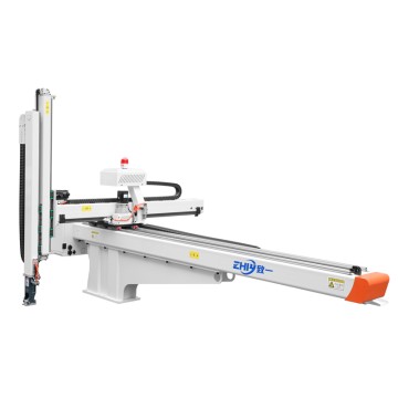
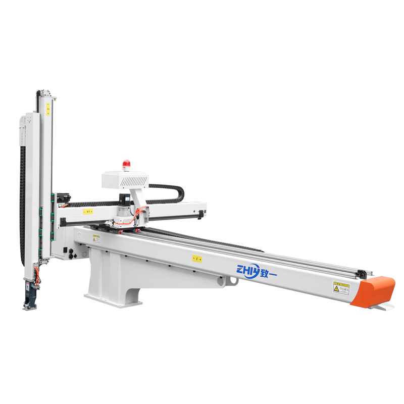
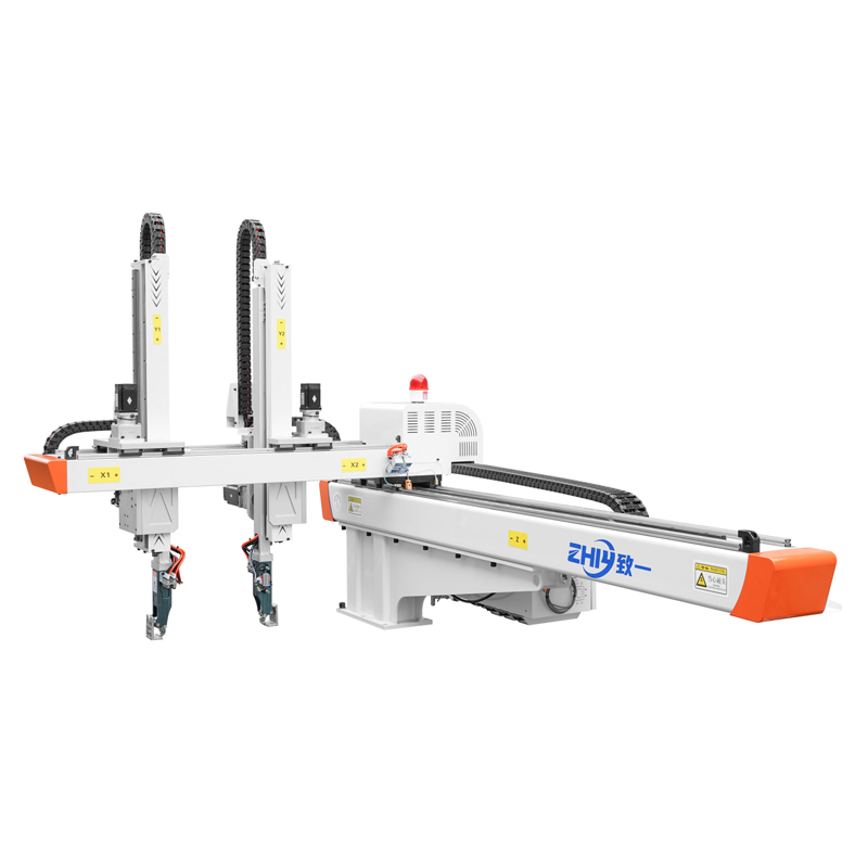
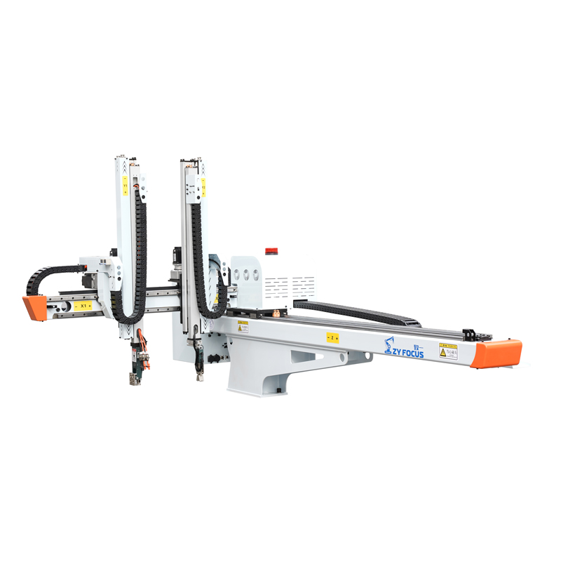
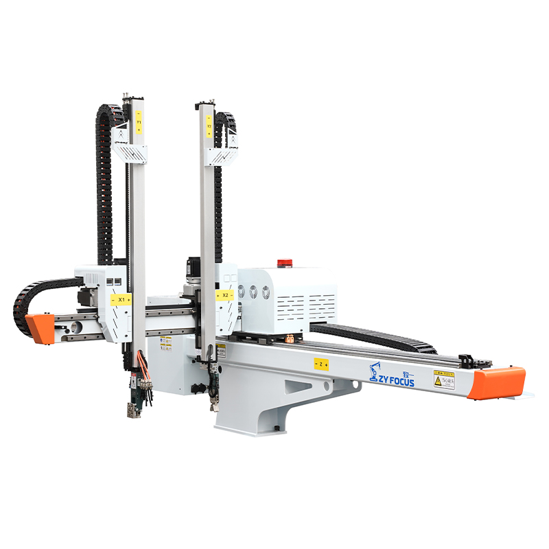
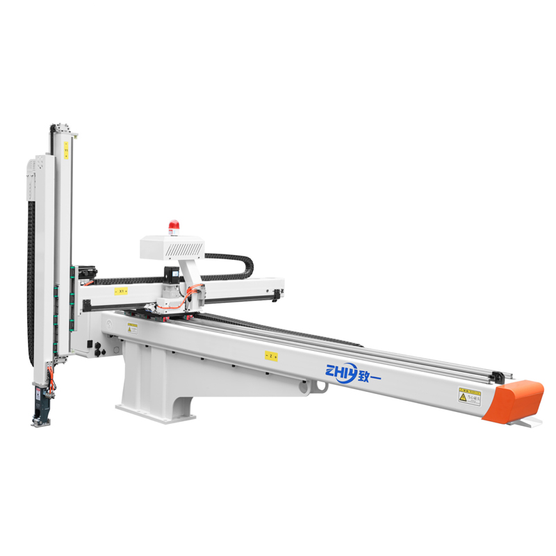
A 3‑axis servo robot operates along X, Y and Z linear axes, driven by closed‑loop servo motors. It is purpose‑built for pick‑and‑place extraction tasks from injection molds, transporting finished automotive parts toward conveyors, stacking stations or simple secondary work cells. It does not offer rotational articulation, which defines its suitable and unsuitable use‑cases in automotive production.
How 3‑Axis Servo Robotic Arms Work Within Molding Workflows
In a typical automotive molding cycle, the sequence begins once the injection press completes cooling and mold opening. The 3‑axis robotic arm travels horizontally into the open mold space along the traverse axis (X). The vertical Z axis descends so the end‑of‑arm tooling (vacuum cups or mechanical grippers) can safely contact the molded automotive part.
Once secure, the arm retracts vertically, pulls back horizontally out of the mold cavity, then moves across to a designated drop‑off position. It releases the finished part, resets to a home position, and signals the Injection Molding Machine to close the mold for the next shot.
All movements are fully programmable. Operators set acceleration, deceleration, travel speeds and stroke limits through a human‑machine interface. The closed‑loop servo system continuously feeds position data back to the controller, correcting small deviations in real‑time and preserving repeatability across thousands of production cycles.
Unlike complex multi‑articulated robots, 3‑axis servo units mount directly atop the injection molding machine beam. This installation footprint avoids large floor‑space requirements, making retrofitting onto existing molding presses far simpler. Commissioning timelines are generally short; qualified technicians can complete setup and basic program teaching within days instead of weeks for most standard applications.
Real‑World Automotive Component Use‑Cases
3‑axis servo robotic arms deliver the strongest return for automotive parts that require linear extraction without complex re‑orientation after demolding.
Interior trim components Door panel inserts, instrument panel small sub‑parts, console trim covers, and seat adjustment plastic housings are ideal matches. These parts demand scratch‑free surface handling and consistent cycle times. 3‑axis arms reliably extract finished trim pieces and place them onto outgoing conveyor belts feeding downstream inspection or packaging stations.
Light‑to‑medium structural plastic parts Battery housing covers, connector housings, wiring grommet bodies and small bumper reinforcement inserts fall within typical 3‑axis payload ranges. Where part weight and size stay within robot rated capacity, these robots remove heavy components without operator lifting and associated workplace‑safety risks.
Multi‑cavity small automotive hardware Sensor brackets, fastener retainers, clip bases and small electrical enclosures often run in high‑cavity molds. The robot removes complete shot sets, separates runners from finished goods, and stacks parts into bins, eliminating repetitive manual sorting work.
It is important to set clear boundaries. Parts that require flipping, rotating, or complex in‑mold insert placement are not well‑suited for pure 3‑axis configurations. For those tasks, manufacturers typically evaluate 5‑axis servo robotic systems instead.
Core Benefits for Automotive Molding Operations
Consistent Cycle Performance
Servo‑driven motion delivers repeatable extraction timing shift‑after‑shift. Even minor cycle‑time improvements compound heavily in high‑volume automotive production, raising overall equipment effectiveness (OEE) by reducing injection‑machine idle waiting time for manual part removal.
Improved Part Quality & Yield
Human handling is a common source of cosmetic defects such as scuffs and indentations on visible automotive trim. Programmable, smooth robotic motion reduces surface‑damage incidents. Closed‑loop positioning maintains repeatability, supporting the tight dimensional consistency required for automotive component acceptance standards.
Reduced Workplace Risk
Automotive molding often produces relatively heavy plastic components. Removing these manually creates ergonomic strain and injury potential for shop‑floor staff. Robotic extraction keeps operators away from hot mold openings and eliminates heavy lifting during part take‑off.
Predictable Total‑Cost‑of‑Ownership
Compared to higher‑axis robotic solutions, 3‑axis servo systems carry moderate upfront investment. Their mechanical structure uses standardised components, keeping spare‑part costs and routine maintenance requirements manageable for mid‑size molding businesses. Many models also deliver measurable energy savings against older pneumatic manipulator alternatives.
Fast Retrofit Compatibility
Mounted to existing injection‑machine beams, these robots integrate into established production layouts without major factory reconstruction work. This allows automotive molders to automate selected presses incrementally instead of replacing an entire production hall at once.
Key Limitations to Keep In Mind
No automation platform fits every automotive molding challenge, and understanding constraints helps avoid poor purchasing decisions.
- No rotational movement: Since 3‑axis arms only perform linear X‑Y‑Z travel, they cannot flip or twist components. If your workflow requires part rotation after extraction, you will need auxiliary fixtures or consider moving to a 5‑axis servo robot design.
- Payload and stroke boundaries: Every robot has defined maximum payload, horizontal reach and vertical stroke. Payload ratings must account not only for the automotive part itself but also the weight of grippers, suction assemblies and fixture hardware. Procurement teams should build in a 10‑20 % safety margin for real‑world production conditions.
- Complex in‑mold operations are limited: Simple part take‑out works excellently, but sophisticated in‑mold insert loading or multi‑step post‑molding manipulation stretches 3‑axis capability. Highly complex processes are better served by higher‑axis robotic hardware.
- End‑of‑arm tooling design remains critical: Even a high‑quality 3‑axis robot will under‑perform if the gripper or vacuum tooling is poorly engineered for your specific automotive part geometry.
Critical Buying Criteria for Procurement Teams
When your team evaluates 3‑axis servo robotic arms for automotive molding applications, focus evaluation on these practical, production‑oriented parameters:
Payload capacity with safety marginCalculate total moving mass including component plus tooling. Never select A Robot operating right at its published maximum payload; running near‑maximum rating accelerates mechanical wear and shortens service life.
Stroke coverage matching your press and mold setup Check traverse, crosswise and vertical stroke dimensions. The robot must fully enter the mold opening, clear machine tie bars, and reach your drop‑off location (conveyor, bin or station). Too‑short stroke creates production bottlenecks; over‑specifying stroke adds unnecessary cost and weight.
Repeatability specification Automotive components demand stable positioning consistency. Review published repeatability figures, and cross‑reference against your part‑quality requirements. Interior cosmetic parts demand tighter repeatability than simple non‑visible structural pieces.
Controller usability and connectivity Look for intuitive HMI interfaces that your shop‑floor technicians can program and adjust without extensive specialist training. Check whether the system offers signal‑exchange compatibility with your existing injection‑machine controls. If your facility uses factory‑MES monitoring systems, confirm available communication interfaces.
Certification and compliance Industrial equipment intended for automotive supply chains should meet widely‑accepted safety standards. Verify documentation such as CE certification, documented safety interlocks, collision‑detection functions, and over‑travel protection features built into the robot design.
Local service and spare‑part availability For continuous automotive production, after‑sales response matters as much as base hardware specifications. Evaluate lead‑times for spare components and access to technical support for commissioning, troubleshooting and scheduled maintenance.
Integration and Operational Best Practices
Even well‑specified robotic hardware will under‑deliver without careful implementation. Follow these proven operational practices for automotive molding lines:
- Customise end‑of‑arm tooling to your part family Generic grippers rarely work optimally across diverse automotive parts. Work with your equipment supplier to design vacuum or mechanical tooling matched to the surface geometry, fragility and weight of your target components.
- Develop structured operator training Make certain shift‑team members understand basic program editing, home‑position reset, emergency‑stop procedures and daily inspection checklists. Robots perform best when staff know both their capabilities and operational limits.
- Build in regular preventive‑maintenance routines Schedule periodic checks on guide rails, belts, servomotor connections and cable chains. Proactive maintenance prevents unexpected downtime during tight automotive‑order delivery windows.
- Validate safety interlock workflows Test safety‑gate interlocks, collision detection and emergency‑stop circuits whenever you install a new mold or modify robot programs. In automotive‑molding environments, unplanned robot‑to‑mold collisions can cause very expensive mold damage.
- Document robot programs for each automotive part number Store and version‑control programs tied to specific molds and components. This shortens change‑over time when switching between different automotive‑part production runs.
Final Thoughts: Is a 3‑Axis Servo Robotic Arm Right For Your Line?
3‑axis servo robotic arms deliver compelling value for automotive injection‑molding operations focused on high‑volume pick‑and‑place extraction. Where your parts do not require complex rotation or elaborate in‑mold secondary processes, these robots offer stable cycle times, improved finished‑part quality, better shop‑floor safety, and a balanced capital‑investment profile.
If your production frequently calls for part flipping, intricate insert loading or multi‑angle manipulation, a 5‑axis servo robotic arm may be the more appropriate automation path. Many automotive molders deploy a mixed fleet: utilising cost‑effective 3‑axis units for straightforward component families and higher‑axis robots for more complex jobs.
When you assess new automation, ground decisions in your actual part portfolio, existing injection‑press specifications, available floor layout, and long‑term service support. By matching robotic capability to real‑world production requirements, automotive molding facilities can realise meaningful efficiency gains without over‑investing in features they will never use.